FZN21A-12D Indoor High-Voltage Vacuum Load Break Switch - featured

FZN21A-12D Indoor High-Voltage Vacuum Load Break Switch

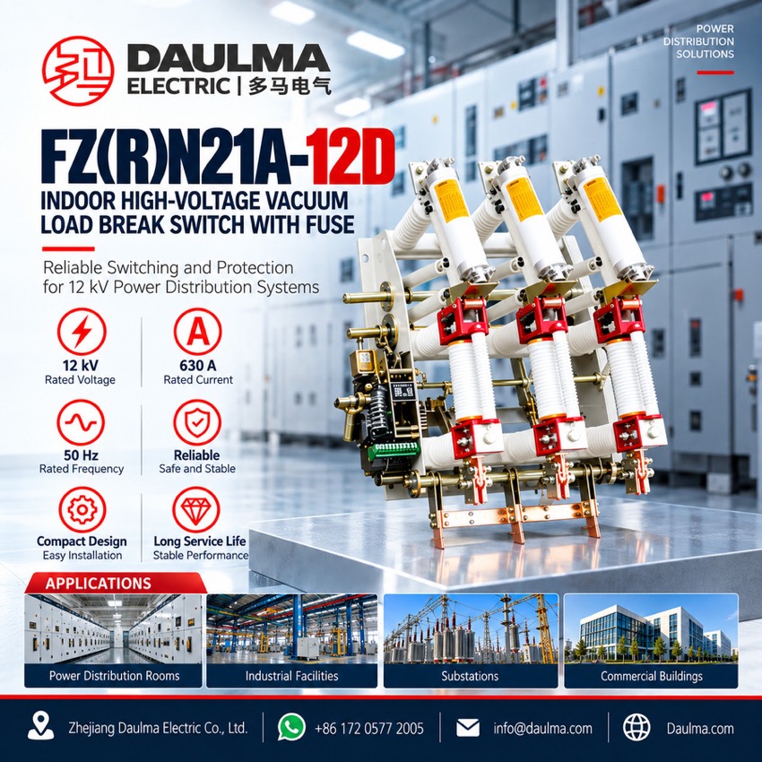
FZN21A-12D Indoor Vacuum Load Break Switch, 12 kV 630 A

  • 630 A switch current, 125 A on the combination unit
  • 20 kA short-time withstand on the switch frame
  • 31.5 kA short-circuit breaking on the fused unit
  • Visible isolation gap and earthing switch with making
  • Motor-charged spring mechanism for remote operation
  • Built into cubicles, ring main units, package substations

Product Overview

The FZN21A-12D indoor high-voltage vacuum load break switch and the FZRN21A-12D switch-fuse combination unit serve three-phase AC 50 Hz distribution systems of 10 kV, where 12 kV is the rated voltage of the switchgear. The switch breaks rated and overload current at 630 A, while the combination unit clears short-circuit current at 31.5 kA and keeps plant from running on two phases. Compact and light, the units are built into cubicles, ring main units and package substations for urban network work, industry, and high-rise and public buildings, as a ring supply unit or a terminal unit.

Product Display
FZN21A-12D Indoor High-Voltage Vacuum Load Break Switch - display

FZN21A-12D Indoor High-Voltage Vacuum Load Break Switch - poster_display

Model Designation

FZN21A-12D Indoor High-Voltage Vacuum Load Break Switch - model

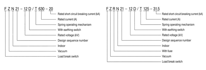
Model format: FZN21A-12D/T 630-20 (load break switch) and FZRN21A-12D/T 125-31.5 (switch-fuse combination unit)

  • F: load break switch; Z: vacuum; N: indoor
  • 21A: design sequence number
  • 12: rated voltage, kV (applied in three-phase AC 50 Hz systems of 10 kV)
  • D: with earthing switch; T: with spring operating mechanism
  • 630: rated current of the switch, A; 20: rated short-time withstand current, kA
  • R: with fuse; 125: rated current of the combination unit and of its fuse, A; 31.5: rated short-circuit breaking current, kA

Service Conditions

  • Ambient temperature: +40 °C upper, -25 °C lower
  • Altitude: not more than 1000 m
  • Relative humidity: daily average not more than 95%, monthly average not more than 90%
  • Seismic intensity: not more than 8 degrees
  • Site condition: no fire, explosion hazard, chemical corrosion or violent vibration
  • Pollution level: II

Construction

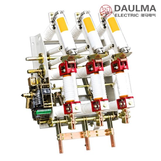
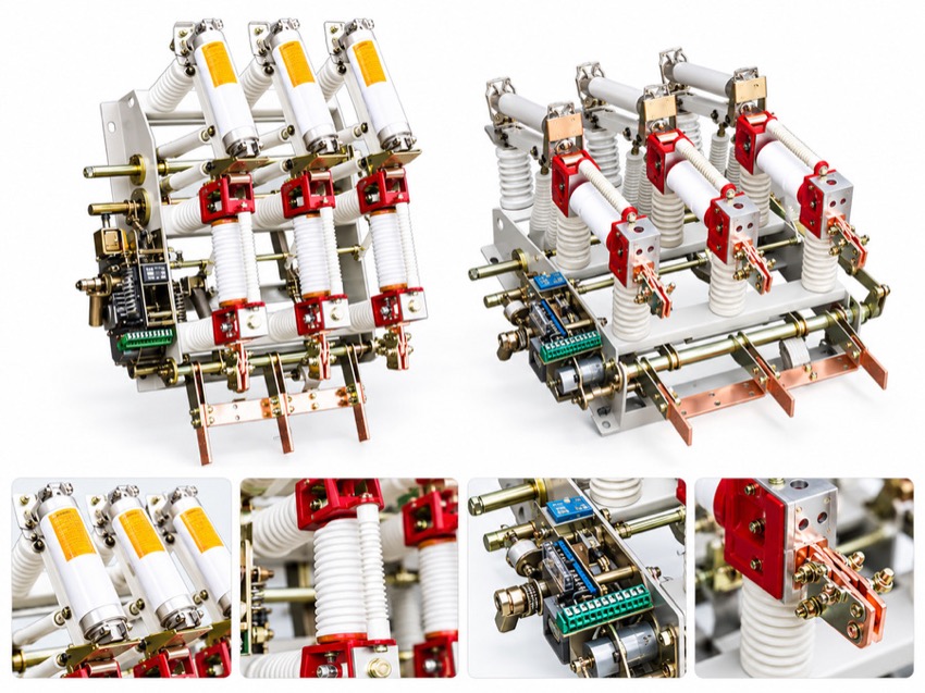
The three poles stand on a common steel frame carried on the lower support frame and insulators, which holds the live parts clear of the frame and keeps the unit compact. The operating mechanism turns the main shaft and the drive linkage, and the insulating pull rods carry that movement to the contacts of the vacuum chamber.

The isolating switch gives the visible isolation gap, and the earthing blade, working against the static earthing contact head, bonds the de-energised side before maintenance. Mechanical interlocks between switch, earthing switch and fuse compartment meet the five-prevention requirements.

The closing energy comes from a charged closing spring, so contact speed is set by the mechanism rather than by the operator. With the motor-charged mechanism the spring is restored from the control supply, giving remote operation, remote signalling and tripping on a relay command, while manual operation stays available if that supply is lost. The release device acts on the signal from the fuse, which is how the combination unit reports the loss of a phase.

Technical Data

No. Item Unit Value
1 Rated voltage kV 12
2 Rated frequency Hz 50
3 Rated current, load break switch FZN21A-12D/T 630-20 A 630
4 Rated current, combination unit FZRN21A-12D/T 125-31.5 A 125
5 Rated short-time withstand current, load break switch kA 20
6 Rated short-circuit breaking current, combination unit kA 31.5
Selection note: the design follows IEC 60265-1/FDIS, IEC 60420, GB 16926 and GB 3804. The table lists the ratings marked on the designation page; the complete type parameter schedule, including the power-frequency and lightning impulse withstand voltages, the making and breaking currents, the mechanical characteristics and the internal arc values, is issued with the order and confirmed against the approved type-test report. Non-standard current or fuse combinations are subject to agreement between manufacturer and purchaser.

Standards

The design follows IEC 60265-1/FDIS, IEC 60420, GB 16926 and GB 3804.

Technical note: the complete type parameter schedule is issued with the order and confirmed against the approved type-test report.

Installation & Dimensions

Installation Diagram
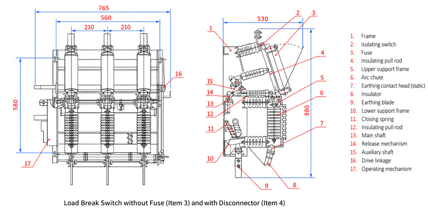
FZN21A-12D Indoor High-Voltage Vacuum Load Break Switch - installation

The unit is bolted to the cubicle frame on its lower support frame. Before energisation, check the closed, open and earthed positions and the interlocks on all three poles, fit the specified fuse of the 125 A class with its striker engaging the release device, and measure the main circuit resistance and the contact travel.

View / dimension Value (mm)
Front view overall width 765 (560 marked inside)
Pole pitch, adjacent poles 210, marked twice
Front view vertical 580
Side view across top 530
Side view vertical 880
Panel cut-outs and busbar drilling see outline drawing
Safety notice: installation, operation and maintenance must be performed by qualified professionals. Before maintenance, open the load break switch, close the earthing switch and verify absence of voltage. Do not use the load break switch alone to interrupt short-circuit current; that duty belongs to the fuse of the combination unit, and a blown fuse is replaced only with the same rated type.

FAQs

It is an indoor three-phase vacuum load break switch for 50 Hz distribution systems of 10 kV, used to make and break rated and overload current, to isolate the circuit through a visible gap and to earth the de-energised side for maintenance. The FZRN21A-12D combination unit adds fuses so the same frame also clears short-circuit current and protects a transformer or cable feeder.

F is the load break switch, Z the vacuum medium, R indicates combined fuses, N indoor use, 21A the design sequence number, 12 the rated voltage in kV, D the earthing switch and T the spring operating mechanism. The trailing numbers give 125 A as the rated current of the combination unit and of its fuse, and 31.5 as the rated short-circuit breaking current in kA. Without the R, FZN21A-12D/T 630-20 describes the switch alone at 630 A and 20 kA.

They are two different quantities. 12 kV is the rated voltage of the switchgear, the voltage class the insulation and the vacuum chamber are designed for, while 10 kV names the three-phase AC 50 Hz distribution system the unit is applied in. A higher voltage class is normally selected so the insulation and switching duties carry margin.

Both are indoor 12 kV vacuum units with a 630 A switch and a 125 A combination unit, so either suits a comparable feeder. The FZN16A-12D is the earlier frame and its data sheet publishes the wider family of breaking currents. The FZN21A-12D is built around a motor-charged spring mechanism with remote operation and signalling, an isolating switch with a visible gap and an earthing switch with making capacity.

For the higher voltage the FZN21-40.5 is the indoor unit of this family for 40.5 kV and the 35 kV side of box-type substations, on a 1250 A frame, and its combination unit clears 20 kA. The FZN25-12DG stays at 12 kV and covers the larger current frames. None can be substituted across the voltage class, because insulation levels, fuse class and clearances are designed for one class only.

Yes. The spring mechanism is charged by an electric motor from the control supply, so the switch can be closed and tripped from a remote control point and can respond to a protection command, while manual operation stays available if that supply is lost. Maintenance follows the usual routine: open the switch, close the earthing switch and verify absence of voltage before any work.

Inquiry for FZN21A-12D Indoor High-Voltage Vacuum Load Break Switch:

Send your project requirements. Our team will reply with technical details and quotation.

Fast response Technical support OEM / ODM