Product Overview
The JDZ(X)7-10 / UNEZ7-6 / UNEZ7-10 indoor epoxy cast-resin voltage transformer is a single-phase medium-voltage voltage transformer designed for voltage measurement, electric energy metering, relay protection and automatic control circuits. It converts high voltage into a standard low-voltage signal for instruments, relays and control equipment in indoor switchgear.
This product should be clearly separated from the previous JSZW three-phase voltage transformer pages. JDZ(X)7-10 is a single-phase VT, selected phase by phase and suitable for V-V or Y-Δ wiring schemes. It is more flexible for single-phase replacement projects, metering cabinets and switchgear circuits where each phase or each wiring group is configured independently.
For international product pages, the voltage class can include 6kV, 10kV, 11kV and 12kV class. Although the catalogue model is JDZ(X)7-10 and UNEZ7-6 / UNEZ7-10, export projects may require 11kV or 12kV class wording. Final voltage ratio, insulation level, accuracy class and wiring method shall be confirmed according to the project specification and approved nameplate.
Product Type
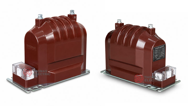
Product Show
7-10, UNEZ7-6/10 Indoor Epoxy Cast-Resin Voltage Transformer Thomas Electric")
7-10, UNEZ7-6/10 Indoor Epoxy Cast-Resin Voltage Transformer Thomas Electric")
7-10, UNEZ7-6/10 Indoor Epoxy Cast-Resin Voltage Transformer Thomas Electric")
7-10, UNEZ7-6/10 Indoor Epoxy Cast-Resin Voltage Transformer Thomas Electric")
| Item | Specification |
|---|---|
| Product name | Indoor Single-Phase Epoxy Cast-Resin Voltage Transformer |
| Model series | JDZ(X)7-10 / UNEZ7-6 / UNEZ7-10 |
| Structure | Indoor epoxy cast-resin insulated single-phase voltage transformer |
| Voltage class | 6kV, 10kV, 11kV and 12kV class medium-voltage systems |
| Rated frequency | 50Hz / 60Hz |
| Rated voltage ratio | 6/√3 : 0.1/√3 : 0.1/3; 10/√3 : 0.1/√3 : 0.1/3; 11/√3 : 0.11/√3 : 0.11/3 by project requirement |
| Accuracy classes | 0.2, 0.5, 1.0, 3.0 for metering and measurement; 3P / 6P by project requirement |
| Rated insulation level | 7.2/32/60kV for 6kV class; 12/42/75kV for 10kV, 11kV and 12kV class |
| Maximum output | 350VA reference |
| Typical use | Voltage measurement, energy metering, relay protection and automatic control circuits |
Applications
- 6kV, 10kV, 11kV and 12kV class indoor medium-voltage switchgear
- Voltage measurement and electric energy metering circuits
- Relay protection and voltage monitoring circuits
- Automatic control equipment and signal acquisition circuits
- Single-phase VT replacement projects in existing switchgear
- V-V wiring systems using two single-phase voltage transformers
- Y-Δ wiring systems using three single-phase voltage transformers with residual-voltage output
Features
- Single-phase design: Unlike JSZW three-phase integrated VTs, this model is selected and installed phase by phase.
- Epoxy cast-resin insulation: The fully cast body provides insulation strength, mechanical stability and moisture resistance for indoor service.
- Flexible wiring options: The product can be used in V-V wiring or Y-Δ wiring according to the measurement and protection scheme.
- Metering and protection support: Accuracy classes such as 0.2, 0.5, 1.0 and 3.0 are available for different applications.
- International voltage coverage: The product page can include 6kV, 10kV, 11kV and 12kV class wording for IEC-oriented export projects.
- Compact terminal arrangement: Front secondary terminals with protective cover make wiring and maintenance easier inside the switchgear.
Service Conditions
- Installation location: indoor medium-voltage switchgear
- Rated frequency: 50Hz / 60Hz
- Ambient temperature: -25°C to +40°C
- Installation environment should be free from severe vibration, conductive dust, corrosive gas, explosive medium and heavy pollution.
- For tropical, high-altitude, high-humidity or coastal projects, insulation level and creepage distance should be confirmed before ordering.
Working Principle
The JDZ(X)7-10 / UNEZ7 voltage transformer operates according to electromagnetic induction. The primary winding is connected to the medium-voltage circuit, and the secondary winding outputs a reduced standard voltage signal for voltage meters, energy meters, relays and control devices. The transformer isolates the secondary low-voltage circuit from the primary medium-voltage system.
Because this is a single-phase VT, the final system connection depends on the project wiring method. Two units may be used for V-V connection, while three units may be used for Y-Δ connection. The selection must consider voltage ratio, insulation level, rated burden, accuracy class, residual-voltage requirement and system grounding mode.
Model Designation
| Code | Meaning |
|---|---|
| J | Voltage transformer / potential transformer |
| D | Single-phase structure |
| Z | Epoxy resin casting insulation |
| X | Auxiliary or residual-voltage winding reference, depending on factory designation |
| 7 | Design sequence code |
| 10 | 10kV class catalogue reference; can be documented for 11kV / 12kV class by project confirmation |
| UNEZ7-6 / UNEZ7-10 | Related model reference used for equivalent indoor cast-resin voltage transformer applications |
Technical Data
| Item | Specification |
|---|---|
| Model series | JDZ(X)7-10 / UNEZ7-6 / UNEZ7-10 |
| Rated voltage class | 6kV, 10kV, 11kV and 12kV class indoor systems |
| Rated insulation level | 7.2/32/60kV for 6kV class; 12/42/75kV for 10kV, 11kV and 12kV class |
| Rated frequency | 50Hz / 60Hz |
| Ambient temperature | -25°C to +40°C |
| Voltage transformer type | Indoor single-phase epoxy cast-resin inductive voltage transformer |
| Rated voltage ratio | 6/√3 : 0.1/√3 : 0.1/3; 10/√3 : 0.1/√3 : 0.1/3; 11/√3 : 0.11/√3 : 0.11/3 by agreement |
| Direct line voltage ratio option | 6/0.1 or 10/0.1 for JDZ7-type applications |
| Accuracy class | 0.2, 0.5, 1.0, 3.0; 3P / 6P by project requirement |
| Maximum output | 350VA reference |
| Applicable standards | IEC 61869-3, IEC 61869-1, GB/T 20840.3-2013, GB/T 20840.1-2010 and project-specific requirements |
Selection Table
The following table is adapted from the catalogue data and expanded with international 11kV / 12kV class guidance.
| Model | Rated
Voltage |
Rated I
nsulation |
Accuracy
Class |
Maximum Output |
|---|---|---|---|---|
| JDZX7-10/160 UNEZ7-6 |
6/√3 : 0.1/√3 : 0.1/3 6.3/√3 : 0.1/√3 : 0.1/3 |
7.2 / 32 / 60kV | 0.2 / 3P: 20 / 60VA 0.2 / 6P: 20 / 60VA 0.5 / 3P: 50 / 60VA 0.5 / 6P: 50 / 60VA |
350VA |
| JDZX7-10/160 UNEZ7-10 |
10/√3 : 0.1/√3 : 0.1/3 11/√3 : 0.11/√3 : 0.11/3 by agreement |
12 / 42 / 75kV | 0.2 / 3P: 20 / 60VA 0.2 / 6P: 20 / 60VA 0.5 / 3P: 50 / 60VA 0.5 / 6P: 50 / 60VA |
|
| JDZ7-10/160 UNEZ7-6 |
6 / 0.1 | 7.2 / 32 / 60kV | 0.2: 20VA 0.5: 50VA 1.0: 80VA 3.0: 150VA |
|
| JDZ7-10/160 UNEZ7-10 |
10 / 0.1 11 / 0.11 by agreement 12 / 0.11 by agreement |
12 / 42 / 75kV | 0.2: 20VA 0.5: 50VA 1.0: 80VA 3.0: 150VA |
Note: Rated output and its relative accuracy class should be selected as matched options. Parameters beyond the catalogue range may be determined by technical agreement between manufacturer and purchaser.
Wiring Options
| Wiring Method | Configuration | Application Note |
|---|---|---|
| V-V | Two single-phase voltage transformers connected between phases | Used for three-phase voltage measurement with two VT units and simplified installation. |
| Y-Δ | Three single-phase voltage transformers with residual-voltage output | Used when phase voltage and residual-voltage / earth-fault detection are required. |
| Single-phase direct voltage | One VT connected according to voltage ratio and system requirement | Used for single-phase metering, monitoring or control signal applications. |
Windings
7-10, UNEZ7-6/10 Indoor Epoxy Cast-Resin Voltage Transformer Thomas Electric")
The JDZ(X)7-10 / UNEZ7 series can be supplied with measurement secondary windings and residual-voltage windings depending on the selected model. Typical terminal marking includes A / N or A / B for the primary side, and a / n, a / b, or da / dn for secondary and residual-voltage circuits.
| Terminal | Function | Engineering Note |
|---|---|---|
| A / N | Primary phase-to-neutral connection | Used for JDZX-type phase voltage ratio applications. |
| A / B | Primary phase-to-phase connection | Used for V-V or line-voltage applications. |
| a / n | Secondary voltage output | Connected to meters, relays, monitoring devices or control equipment. |
| a / b | Secondary output for V-V wiring | Used where two single-phase VTs form a V-V connection. |
| da / dn | Residual-voltage output | Used for earth-fault detection or open-delta protection circuits. |
Dimensions
| Dimension Item | Reference Value | Engineering Note |
|---|---|---|
| Overall length | 350mm reference | Main length reference from outline drawing. |
| Base length | 315mm / 290mm / 265mm reference | Used for mounting layout and cabinet space check. |
| Overall height | 252mm reference | Confirm top terminal clearance before installation. |
| Width | 160mm reference | Used for switchgear side clearance. |
| Mounting hole | 4-Φ16 reference | Mounting hole position should follow the approved drawing. |
| Terminal spacing | 175mm reference between top terminals | Confirm phase clearance and cable/busbar connection. |
| Weight | Approx. 28kg reference | Actual weight depends on final ratio and structure. |
Standards and Compliance
The JDZ(X)7-10 / UNEZ7 series voltage transformer can be specified according to IEC 61869-3 for inductive voltage transformers and IEC 61869-1 for general instrument transformer requirements. Catalogue references also include GB/T 20840.3-2013 and GB/T 20840.1-2010. For export product pages, IEC wording is preferred, while GB references can remain as factory design and test references.
Installation and Dimensions
7-10, UNEZ7-6/10 Indoor Epoxy Cast-Resin Voltage Transformer Thomas Electric")
The product is installed inside indoor switchgear using the base mounting holes shown in the outline drawing. Before cabinet production, confirm top terminal clearance, secondary terminal direction, grounding point, mounting hole distance, wiring scheme and access space for maintenance. When using V-V or Y-Δ wiring, the number of VT units and terminal connection must be confirmed with the approved wiring diagram.
Safety Notes
- Confirm voltage class, voltage ratio, insulation level, accuracy class and rated output before production.
- Select JDZ or JDZX structure according to whether residual-voltage output is required.
- Secondary circuits of voltage transformers shall not be short-circuited during operation.
- Secondary circuits should be protected by suitable fuses or miniature circuit breakers.
- Before maintenance, de-energize the primary circuit and follow lockout/tagout safety procedures.
- One point of the secondary circuit should be grounded according to project electrical safety practice.
- Installation and commissioning shall be performed by qualified medium-voltage electrical personnel.