Product Overview
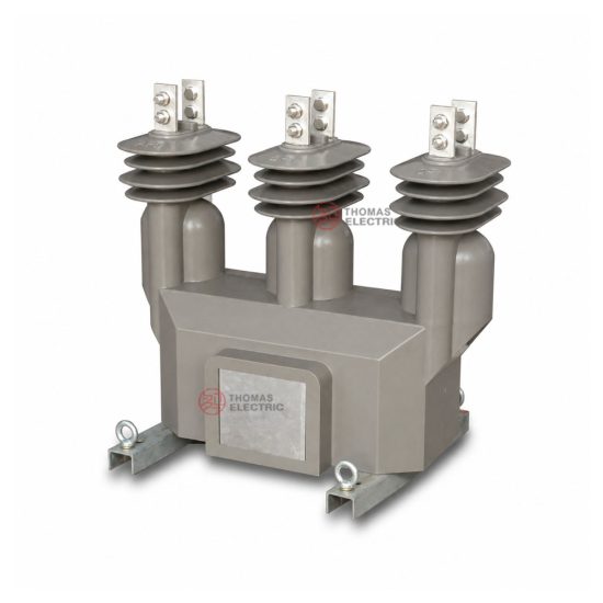
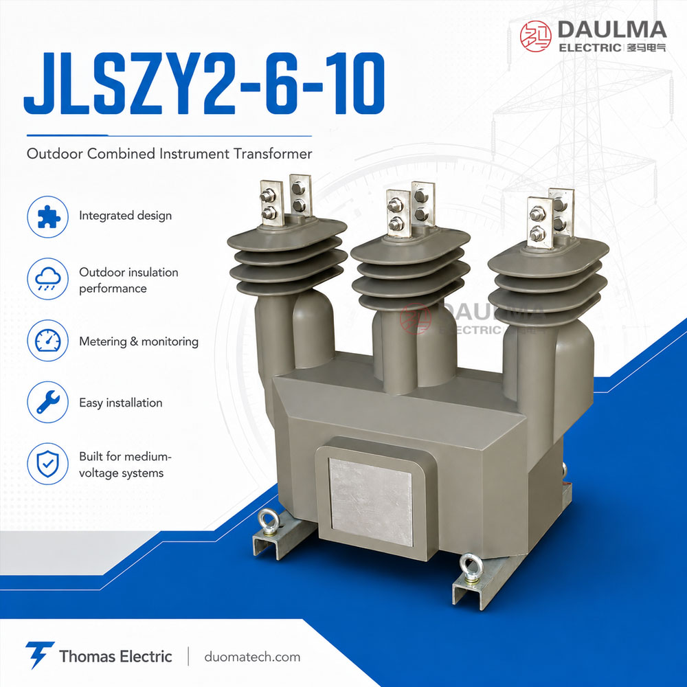
JLSZY2-6/10 is an outdoor epoxy cast-resin combined instrument transformer designed for medium-voltage distribution metering. It integrates voltage transformer (PT/VT) elements and current transformer (CT) elements into one compact unit, providing voltage and current signals for electric energy metering, power monitoring and revenue measurement.
This model is suitable for 6kV and 10kV three-phase AC distribution networks. Compared with JZZV1-10, which is usually described as a three-phase two-element combined metering transformer, JLSZY2-6/10 should be positioned as a three-phase three-component outdoor combined transformer. It is designed for outdoor pole-mounted metering, outdoor metering cabinets, compact substations and utility distribution metering points.
Product Display
Application Position
JLSZY2-6/10 is installed at the medium-voltage metering point of the distribution network. Typical positions include utility poles, outdoor metering boxes, compact substations and the high-voltage side of distribution transformers. The transformer supplies secondary voltage and current signals to active and reactive energy meters.
Main Applications
- 6kV and 10kV outdoor distribution networks
- 7.2kV and 12kV class medium-voltage metering systems
- Pole-mounted high-voltage metering points
- Outdoor metering cabinets and compact substations
- Active and reactive energy measurement
- Utility revenue metering and industrial user metering
- Distribution transformer high-voltage side metering
Key Specifications
| Item | Specification |
|---|---|
| Model series | JLSZY2-6 / JLSZY2-10 |
| Product type | Outdoor combined instrument transformer / PT CT combined transformer |
| Structure | Three-phase three-component combined transformer |
| Transformer components | Voltage transformer units and current transformer units |
| Insulation structure | Outdoor epoxy cast-resin insulation |
| Installation | Outdoor pole-mounted, outdoor cabinet or substation installation |
| System voltage | 6kV and 10kV systems |
| International voltage class | 7.2kV and 12kV classes |
| Rated frequency | 50Hz / 60Hz |
| Ambient temperature | -15°C to +55°C sample condition |
| Altitude | Not more than 4500m sample condition |
| Voltage transformer ratios | 6/√3 / 0.1/√3 / 0.1/3; 10/√3 / 0.1/√3 / 0.1/3; 11/√3 / 0.11/√3 / 0.11/3 |
| Voltage transformer accuracy | 0.2 / 0.5 |
| Current transformer primary current | 5A to 800A |
| Current transformer secondary current | 5A or 1A according to project specification |
| Current transformer accuracy | 0.2S / 0.2 / 0.5 |
| Rated insulation level | 7.2/32/60kV or 12/40/75kV according to model |
Application Fit
Suitable For
- Outdoor 6kV and 10kV high-voltage metering points
- 12kV class distribution metering where PT and CT signals must be integrated in one unit
- Three-phase three-element metering schemes
- Pole-mounted metering installations
- Outdoor metering cabinets and compact substations
- Projects requiring 5A or 1A CT secondary current output
- High-altitude outdoor applications up to the sample condition of 4500m
Not Recommended For
- Indoor-only compact cabinet projects where a smaller indoor combined transformer is required
- Applications requiring separate CT and VT installation instead of an integrated combined unit
- Protection-only CT applications where metering accuracy is not required
- Systems above 12kV class without technical confirmation
- Oil-immersed metering transformer requirements
- High-frequency electronic transformer applications
Installation Conditions
- Installation location: outdoor pole, outdoor metering cabinet, compact substation or distribution metering point
- Rated frequency: 50Hz / 60Hz power-frequency AC system
- Ambient temperature: -15°C to +55°C sample condition
- Altitude: not more than 4500m sample condition
- Mounting: confirm base dimension, lifting method and primary terminal clearance before installation
- Grounding: connect grounding terminal according to the metering cabinet or pole-mounted equipment scheme
- Maintenance: inspect terminal fastening, secondary box sealing, resin surface and grounding connection periodically
Technical Structure
JLSZY2-6/10 integrates PT and CT functions in one outdoor epoxy cast-resin body. The voltage transformer units provide voltage signals, while the current transformer units provide current signals. The three-phase three-component structure supports complete three-phase metering in outdoor distribution networks.
| Component | Description |
|---|---|
| Outdoor epoxy cast-resin body | Provides insulation, mechanical support and outdoor environmental resistance |
| Voltage transformer units | Provide phase voltage signals for energy meters and monitoring devices |
| Current transformer units | Provide current signals for active and reactive energy meters |
| Primary terminals | Outdoor medium-voltage connection terminals for 6kV or 10kV systems |
| Secondary terminal box | Low-voltage terminal area for PT and CT secondary wiring |
| Mounting base | Base structure for pole-mounted, outdoor cabinet or substation installation |
| Grounding point | Grounding terminal for safe installation and metering system reference |
Model Designation
- J = Combined instrument transformer
- L = Current transformer element
- S = Three-phase structure
- Z = Epoxy cast-resin / dry-type insulation
- Y = With voltage transformer element
- 2 = Design sequence or generation code
- 6 / 10 = Rated system voltage code for 6kV or 10kV applications
Technical Data
The following technical data is organized from the JLSZY2-6/10 product sample. For international product pages, the 6kV version can be expressed as 7.2kV class, and the 10kV version can be expressed as 12kV class.
Voltage Transformer Section
| Rated Voltage Ratio | Accuracy Class | Rated Output | Rated Insulation Level |
|---|---|---|---|
| 6000/√3 / 100/√3 / 100/3V | 0.2 / 0.5 | 30VA | 7.2/32/60kV |
| 10000/√3 / 100/√3 / 100/3V | 40VA | 12/40/75kV | |
| 11000/√3 / 110/√3 / 110/3V | 60VA |
Current Transformer Section
| Rated
Current Ratio |
Accuracy
Class |
Rated
Output |
Short-Time
Thermal Current |
Rated
Dynamic Current |
Rated
Insulation Level |
|---|---|---|---|---|---|
| 5A to 800A / 5A or 1A | 0.2S | 15VA | 60Itn | 150Itn | 12/42/75kV |
| 5A to 800A / 5A or 1A | 0.2 | 15VA | |||
| 5A to 800A / 5A or 1A | 0.5 | 20VA |
Technical notes:
- One combined transformer is supplied with one selected accuracy class and rated output combination.
- The voltage transformer section can provide 100/√3V or 110/√3V secondary voltage according to project system voltage.
- The 100/3V or 110/3V output can be used for residual-voltage or metering-related secondary requirements according to the wiring design.
- The current transformer ratio should be selected according to the line load current and meter input requirement.
- Secondary current can be specified as 5A or 1A.
- If user data exceeds the listed table range, final parameters should be confirmed between manufacturer and purchaser.
Installation and Dimensions
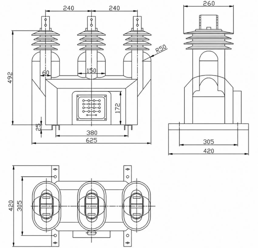
Dimension and Weight Reference
| Item | Reference Value |
|---|---|
| Overall front width | 625mm |
| Primary terminal spacing | 240mm + 240mm reference |
| Overall height | 492mm reference |
| Body lower width | 380mm reference |
| Side base length | 420mm reference |
| Side body width | 305mm reference |
| Plan width | 420mm reference |
| Secondary terminal box | Front-mounted secondary wiring box |
| Primary terminal style | Outdoor flat terminal plates |
| Final weight | Confirm by drawing and model configuration |
Terminal and Wiring Notes
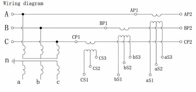
- The sample wiring diagram shows three-phase PT and CT combined metering wiring.
- PT secondary terminals are used for voltage input to meters and monitoring devices.
- CT secondary terminals are used for current input to active and reactive energy meters.
- CT secondary circuits must not be open-circuited during operation.
- Confirm AP, BP, CP primary terminal sequence and secondary polarity before commissioning.
- Grounding and meter box wiring should follow the approved project wiring diagram.
Compliance and Testing
The sample references GB20840.4-2015 and customer-specific requirements. For international projects, the final compliance statement should be aligned with the buyer’s specification, applicable IEC instrument transformer standards and local utility metering rules.
Typical Routine Tests
- Visual inspection and nameplate verification
- CT ratio and polarity test
- VT ratio and polarity test
- CT accuracy test at specified burden
- VT accuracy test at specified burden
- Power-frequency withstand voltage test
- Insulation resistance test
- Secondary terminal and grounding inspection
- Metering wiring and terminal identification verification
- Outdoor sealing and surface inspection
Engineering Notes
- Use JLSZY2-6/10 when the project requires an outdoor integrated PT + CT metering unit.
- For international pages, describe JLSZY2-6 as a 7.2kV class product and JLSZY2-10 as a 12kV class product.
- This model is more suitable for three-phase three-component metering than two-element combined transformer pages.
- Confirm CT primary current, CT secondary current, PT ratio and metering accuracy before ordering.
- Confirm whether the project requires 100V-class or 110V-class secondary voltage output.
- Do not describe this product as a single current transformer or single voltage transformer; its value is the integrated outdoor PT + CT metering structure.
Selection Guide
Select by system voltage: Use JLSZY2-6 for 6kV systems and JLSZY2-10 for 10kV systems. For international pages, write them as 7.2kV and 12kV class combined instrument transformers.
Select by installation position: Choose this product for outdoor pole-mounted metering points, outdoor metering cabinets or substation metering positions where one integrated PT + CT unit is preferred.
Select by current ratio: Determine the CT primary current according to the actual load current. The sample supports a 5A to 800A primary current range, with 5A or 1A secondary current according to meter requirements.
Select by metering accuracy: Use 0.2S CT accuracy for higher-accuracy metering. Use 0.2 or 0.5 where the project metering specification allows it.
Select by voltage ratio: Choose 6/√3 / 0.1/√3 / 0.1/3, 10/√3 / 0.1/√3 / 0.1/3 or 11/√3 / 0.11/√3 / 0.11/3 according to the network voltage and meter input requirement.
Select by inquiry clarity: A clear inquiry should state system voltage, PT ratio, CT primary current, CT secondary current, accuracy classes, rated burden, installation type, altitude condition and quantity.