Product Overview
The LDZ1-10 current transformer is an indoor epoxy resin cast single-turn-through current transformer designed for AC power systems with rated frequency of 50Hz and rated voltage class of 10kV. It is mainly used for current measurement, electric energy metering, and relay protection in indoor medium-voltage switchgear and distribution systems.
The product adopts an annealed ring-core structure. The primary conductor passes through the transformer body as a single-turn primary circuit, while the secondary winding and magnetic core are cast together with epoxy resin for insulation and mechanical protection. The cast body base is provided with a rating plate, earthing bolt, and mounting holes, making it suitable for wall-through installation in fixed indoor switchgear.
For international projects, this product can be positioned for 10kV, 11kV and 12kV class indoor medium-voltage applications, provided that the insulation level, service condition, outline drawing, and project standard are confirmed before selection.
Product Type
| Item | Specification |
|---|---|
| Product name | Indoor Epoxy Resin Cast Single-Turn-Through Current Transformer |
| Model series | LDZ1-10 |
| Product structure | Single-turn-through type, epoxy resin casting insulation, annealed ring-core structure |
| Voltage class | 10kV class; applicable to 10kV, 11kV and 12kV class indoor systems by project confirmation |
| Rated frequency | 50Hz |
| Installation type | Wall-through mounting in fixed indoor switchgear |
| Typical applications | Current measurement, electric energy metering, relay protection, switchgear instrumentation |
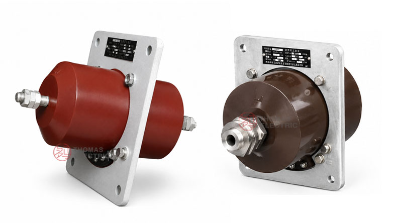
Product Display


Applications
- 10kV, 11kV and 12kV class indoor medium-voltage distribution systems
- Fixed switchgear, feeder cabinets, and indoor power distribution panels
- Current measurement and electric energy metering circuits
- Relay protection and feeder monitoring circuits
- Wall-through installation where the primary conductor passes through the CT body
- Industrial substations, power distribution rooms, and complete electrical equipment
Features
- Single-turn-through design: The primary conductor passes once through the CT body, simplifying the primary circuit arrangement in indoor switchgear.
- Epoxy resin casting insulation: The secondary winding and annealed ring core are cast with epoxy resin to provide insulation stability and mechanical protection.
- Wall-through mounting: The cast body base includes mounting holes for fixed installation in cabinet panels or switchgear structures.
- Metering and protection use: The product is suitable for current measurement, energy metering, and relay protection circuits.
- Integrated grounding and marking: The product body is provided with rating plate position and earthing bolt for safer installation and maintenance identification.
- Indoor medium-voltage application: Suitable for controlled indoor environments where resin-insulated CT construction is required.
Principle
The LDZ1-10 current transformer operates according to electromagnetic induction. When the primary conductor passes through the transformer body and carries current, magnetic flux is generated in the annealed ring core. The secondary winding outputs a proportional current signal for connected meters, relays, or monitoring devices. The epoxy resin casting insulation separates the medium-voltage primary circuit from the low-voltage secondary circuit.
For metering circuits, the CT should be selected according to the required accuracy class, rated burden, and connected instrument load. For relay protection circuits, the current ratio, secondary burden, and protection setting must be coordinated with the system operating current and fault-current level.
Model Designation

The model code can be interpreted as follows:
| Code | Meaning |
|---|---|
| L | Current transformer |
| D | Single-turn-through type |
| Z | Epoxy resin casting insulation |
| 1 | Design sequence code |
| 10 | Rated voltage class: 10kV class |
Technical Data
| Item | Specification |
|---|---|
| Rated voltage class | 10kV class; applicable to 10kV, 11kV and 12kV class indoor systems by project confirmation |
| Rated frequency | 50Hz |
| Insulation type | Epoxy resin casting insulation |
| Core structure | Annealed ring core |
| Primary structure | Single-turn-through type primary conductor arrangement |
| Secondary output | Configured according to metering or relay protection requirement |
| Installation method | Wall-through mounting on fixed switchgear or cabinet structure |
| Service altitude | Not over 1000m under standard service conditions |
| Ambient temperature | -5°C to +40°C |
| Relative humidity | Less than 85% at 20°C reference condition |
| Vibration performance | Passed direct vibration test with 0.4g three sine waves, equivalent to nine-degree earthquake reference |
Selection Table
The final ratio, secondary current, accuracy class, and rated output should be selected according to the connected meter, relay, wiring burden, and switchgear fault-current level. Long table headers are wrapped into multiple lines for responsive website display.
| Selection Item |
Common Requirement |
Engineering Note |
|---|---|---|
| Rated voltage | 10kV class | For 10kV, 11kV and 12kV class indoor systems, confirm insulation level and applicable standard. |
| Rated frequency | 50Hz | 60Hz requirements should be confirmed separately before ordering. |
| Current ratio | Project-specific | Select according to feeder rated current, metering range, and protection setting. |
| Secondary current | 5A or 1A by order | 5A is common for short secondary wiring; 1A may reduce burden in longer wiring circuits. |
| Accuracy class | Metering or protection class | Specify each secondary core separately when both metering and protection functions are required. |
| Rated burden | Project-specific VA | Total meter, relay, and cable burden must not exceed the rated output of the selected core. |
Note: Final technical parameters shall be confirmed according to the nameplate, approved drawing, technical agreement, and factory test report.
Service Conditions
- Installation location: indoor medium-voltage switchgear
- Altitude: not over 1000m under standard service conditions
- Ambient temperature: -5°C to +40°C
- Relative humidity: less than 85% at 20°C reference condition
- The product has passed direct vibration testing with 0.4g three sine waves, equivalent to nine-degree earthquake reference.
- The installation environment should be free from severe vibration beyond specified conditions, corrosive gas, explosive medium, conductive dust, heavy pollution, and abnormal condensation.
Standards and Compliance
The LDZ1-10 current transformer is designed for indoor medium-voltage current transformer applications. Project requirements may specify IEC or GB current transformer standards according to the final technical agreement. Routine inspection normally includes appearance inspection, ratio test, polarity verification, accuracy test, insulation resistance test, and power-frequency withstand test where required.
Installation and Dimensions


The LDZ1-10 current transformer is designed for wall-through installation in fixed switchgear. The base of the cast body includes a rating plate, earthing bolt, and mounting holes. Before cabinet production, the installation hole position, primary conductor path, terminal access, and insulation clearance shall be confirmed with the approved outline drawing.
Dimensions
| Item | Dimension / Note |
|---|---|
| Mounting structure | Wall-through mounting on fixed switchgear or cabinet panel |
| Primary path | Single-turn-through conductor or busbar arrangement |
| Base structure | Cast body base with mounting holes |
| Earthing point | Earthing bolt provided on the product body |
| Drawing confirmation | Final outline and hole dimensions shall be confirmed before cabinet production |
Safety Notes
- Confirm the model, voltage class, current ratio, accuracy class, and rated burden before installation.
- Check wall-through hole position, primary conductor clearance, secondary terminal access, and earthing arrangement before assembly.
- Connect primary and secondary terminals according to terminal markings and the project wiring diagram.
- The secondary circuit of a current transformer must not be open-circuited when the primary circuit is energized.
- Before disconnecting meters or relays, short-circuit the CT secondary circuit using an approved shorting block.
- Installation and maintenance shall be performed by qualified medium-voltage electrical personnel.
Ordering Info
Please provide the following information when ordering or requesting a quotation:
- Product model: LDZ1-10
- Rated voltage and system voltage class
- Rated primary current and rated secondary current
- Accuracy class and rated burden
- Metering or relay protection application requirement
- Installation drawing, wall-through opening, and terminal direction
- Service condition if altitude, humidity, pollution level, or vibration requirement is special
- Quantity, certificates, test reports, labeling, and packaging requirements
Selection Guide
- Confirm voltage class: Select LDZ1-10 for indoor medium-voltage systems around 10kV class, including international 10kV, 11kV and 12kV class applications after insulation confirmation.
- Confirm installation: Use this model when a single-turn-through wall-mounted CT structure is required.
- Select current ratio: Choose the current ratio according to feeder load current, metering range, and protection setting.
- Specify core function: Define whether the secondary circuit is used for measurement, energy metering, or relay protection.
- Check burden: The total burden of meters, relays, and secondary wiring should not exceed the rated output of the CT.
- Confirm drawing: Check wall-through opening, base mounting holes, conductor path, terminal direction, and maintenance access before production.