Product Overview
Functional Definition
The LYM-0.5 Dry type Indoor Current Transformer is a precision electromagnetic instrument designed for accurate current measurement, energy metering, and relay protection in low-voltage AC power systems. Operating on electromagnetic induction principles, this busbar-type transformer provides galvanically isolated secondary current signals proportional to primary current in applications with rated voltage up to 0.5kV and frequency of 50Hz or 60Hz.
Key Ratings Snapshot
| Item | Specification (per order / nameplate) |
|---|---|
| System voltage class | 0.5 kV class (low-voltage distribution and industrial applications) |
| Rated frequency | 50 Hz (60 Hz available upon request) |
| Rated primary current | 750A to 25000A (per model specification) |
| Rated secondary current | 5 A |
| Accuracy class | Class 3 (measurement and protection applications) |
| Rated output | 20 VA (750A-10000A) / 50 VA (15000A-25000A) |
| Burden power factor | cosφ = 0.8 (lagging) unless otherwise specified |
| Insulation level | 0.5/3 kV |
| Core construction | Laminated silicon steel sheet with annealed toroidal core |
| Applicable standards | Q/JB 3375-84 (Shanghai standard); customizable to IEC 61869-1 / IEC 61869-2 |
| Mounting type | Busbar-type with direct mounting holes |
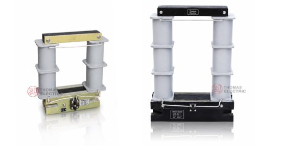
Product Shows

Working Principle
Operating on Faraday’s law of electromagnetic induction, the LYM-0.5 transformer features a toroidal magnetic core constructed from laminated silicon steel sheets. The primary current passes through the busbar aperture, generating magnetic flux in the core. This flux induces proportional voltage in the secondary winding wound around the core, delivering standardized 5A output current through the connected burden. The split secondary winding configuration placed on upper and lower yokes ensures optimal magnetic performance and maintains accuracy class 0.2 or 0.5 across the operational range from 1% to 120% of rated primary current.
System Application Position
- Low-Voltage Distribution: 0.66kV and below AC distribution systems
- Industrial Power Systems: High-current measurement in manufacturing facilities
- Energy Metering: Precise electricity measurement for billing and monitoring
- Protection Circuits: Overcurrent and ground fault protection schemes
- SCADA Integration: Current monitoring in supervisory control systems
Structural Form Overview
Dry-type construction with laminated silicon steel core provides superior magnetic properties and measurement stability. The busbar-type mounting configuration eliminates the need for primary conductor installation while ensuring compact integration in low-voltage switchgear and distribution panels. Varnish-treated windings protect against moisture for enhanced durability and reliability in indoor industrial environments.
Model Designation

Model Code Explanation
- L — Current transformer (CT)
- Y — Measuring type
- M — Busbar-type (no primary winding required)
- 0.5 — Rated voltage class (kV)
Customization Options
The LYM-0.5 series can be customized to meet specific application requirements including adjustments to current transformation ratios, dimensional specifications, accuracy classes (0.2, 0.5), and insulation levels. Wet-heat type variants denoted by “TH” in model designation are available for high-humidity or extreme temperature environments.
Service Conditions
The LYM-0.5 series current transformers are designed for indoor operation under normal service conditions in low-voltage power systems.
- Installation environment: Indoor installation only
- Altitude: Not exceeding 1000 m above sea level (higher altitude applications require engineering confirmation)
- Ambient temperature: −5 °C to +40 °C
- Relative humidity: Not exceeding 85% at +20 °C reference
- Environmental conditions: Free from corrosive gases, vapors, chemical deposits, or explosive media that may affect insulation integrity; no severe vibration, mechanical shock, or impact
Construction
Construction Design
- Structure: Busbar-type for direct mounting on conductors
- Core material: High-quality laminated silicon steel sheets
- Core configuration: Annealed toroidal magnetic core
- Winding arrangement: Split secondary winding on upper and lower yokes
- Winding protection: Varnish treatment for moisture resistance
- Mounting: Secured with clips and equipped with mounting holes
The laminated silicon steel core is stacked and fixed by nips for enhanced stability and durability. Advanced superconducting materials enable high precision maintenance even under varying load conditions ranging from 1% to 120% of rated primary current.
Windings & Terminal Marking
- Primary terminals: P1 / P2 (polarity markings)
- Secondary terminals: S1 / S2
- Grounding provision: Grounding bolt provided
Terminal markings follow standard CT polarity conventions. When primary current flows from P1 to P2, secondary current flows from S1 to S2 through the external circuit, maintaining correct polarity. Correct terminal identification shall be observed to ensure metering and protection performance.
Technical Data
This section provides selection-oriented technical data for the LYM-0.5 series indoor, dry-type current transformer used in 0.5kV class AC systems (50 Hz). Data shown below is intended for preliminary selection based on rated primary current, accuracy class, and rated output capacity.
Definitions: Rated primary current (A) specifies the nominal current flowing through the primary busbar. Rated output (VA) is the transformer’s capacity to deliver power to connected burden at specified accuracy. Insulation level indicates power frequency withstand voltage / lightning impulse withstand voltage.
Notation: Technical parameters shall be verified against nameplate values and factory test report for acceptance.
Technical Specifications per Q/JB 3375-84
| Rated Primary Current (A) | Rated Secondary Current (A) | Frequency (Hz) | Accuracy Class | Rated Output (VA) | Insulation Level (kV) |
|---|---|---|---|---|---|
| 750 – 1000 | 5 | 50 | 3 | 20 | 0.5/3 |
| 1500 – 2000 | 5 | 50 | 3 | 20 | 0.5/3 |
| 2500 – 5000 | 5 | 50 | 3 | 20 | 0.5/3 |
| 7500 – 10000 | 5 | 50 | 3 | 20 | 0.5/3 |
| 15000 | 5 | 50 | 3 | 50 | 0.5/3 |
| 20000 | 5 | 50 | 3 | 50 | 0.5/3 |
| 25000 | 5 | 50 | 3 | 50 | 0.5/3 |
Standards & Normative References
| Standard | Title | Application |
|---|---|---|
| Q/JB 3375-84 | Shanghai Local Standard for Low-Voltage Current Transformers | Primary reference standard |
| IEC 61869-1 | Instrument Transformers – Part 1: General Requirements | General requirements (customizable upon request) |
| IEC 61869-2 | Instrument Transformers – Part 2: Additional Requirements for Current Transformers | CT-specific requirements (customizable upon request) |
| GB/T 20840.1 | Instrument Transformers – Part 1: General Requirements | National standard (aligned with IEC 61869 framework) |
| GB/T 20840.2 | Instrument Transformers – Part 2: Current Transformers | National CT requirements (aligned with IEC 61869-2) |
Factory Testing Compliance
- Routine tests per applicable standard including polarity/marking verification, ratio verification, and accuracy verification at specified burden
- Dielectric tests per insulation coordination requirements
- Visual and dimensional inspection including marking and workmanship conformity
- Type and special tests as required by project specification
Installation & Dimensions

- Outline dimensions and mounting details are provided in the dimensional drawings below.
- The transformer shall be securely mounted using the designated fixing holes on the bottom surface.
- Primary conductor connection is made by passing the busbar through the central aperture.
- Adequate clearance shall be maintained for insulation, heat dissipation, and maintenance access.
- One point of the secondary circuit shall be reliably grounded in accordance with applicable standards.
Outline Dimensions
Overall Dimension Table
| Rated Primary Current (A) | A (mm) | B (mm) | C (mm) | D (mm) | E (mm) | F (mm) | H (mm) | h (mm) |
|---|---|---|---|---|---|---|---|---|
| 750 – 2000 | 102 | 102 | 150 | 250 | 102 | 155 | 255 | — |
| 2000 – 5000 | 140 | 140 | 195 | 295 | 102 | 155 | 305 | — |
| 7500 – 10000 | 120 | 250 | 230 | 365 | 100 | 170 | 360 | 85 |
| 15000 | 120 | 350 | 294 | 360 | 90 | 155 | 400 | 85 |
| 20000 | 120 | 460 | 350 | 405 | 75 | 155 | 620 | 115 |
| 25000 | 200 | 600 | 380 | 480 | 120 | 180 | 760 | 120 |
Safety Notes
- Secondary circuit must never be left open when the transformer is energized, as dangerous high voltage may appear across the secondary terminals.
- During inspection or maintenance, the secondary circuit shall be short-circuited before disconnecting any instruments.
- One point of the secondary circuit should be reliably grounded in accordance with applicable standards.
- All installation and maintenance work shall comply with local electrical safety regulations.
Ordering Information
When placing an order, the required configuration shall be specified according to the local grid requirements, applicable standards, and project technical specification. The following parameters shall be clearly stated for technical confirmation and production release:
- Rated primary current / transformation ratio (e.g., 1000/5A, 5000/5A)
- Rated secondary current (standard: 5 A)
- Accuracy class requirement (standard: Class 3; available: 0.2, 0.5 upon request)
- Rated burden (VA) per application requirement
- Operating frequency (50 Hz standard; 60 Hz available)
- Environmental requirements (standard or wet-heat type “TH”)
- Special requirements (dimensional modifications, terminal arrangements)
Selection Guide
How to select:
1: Determine rated primary current (Ip) based on feeder/load rating and expected continuous operating current.
2: Select accuracy class based on application (Class 3 for protection; 0.2/0.5 for precision metering if required).
3: Confirm rated burden (VA) for secondary circuit based on connected meters/relays and wiring losses.
4: Verify dimensional constraints against available mounting space in switchgear or distribution panel.
If local utility or project requirements apply (e.g., specific insulation levels, IEC/GB standard compliance, terminal arrangement, mounting constraints, documentation language, or required certificates), specify them at the ordering stage. Special configurations shall be confirmed by technical agreement and final data sheet prior to production.
FAQs
Q1: What applications is the LYM-0.5 Current Transformer best suited for?
A: The LYM-0.5 is designed for low-voltage, high-current applications in power systems operating at 0.66kV or lower with frequency of 50Hz. Primary applications include current measurement, energy metering, and relay protection in industrial distribution systems, manufacturing facilities, and commercial power installations.
Q2: What is the rated primary current range for the LYM-0.5?
A: The LYM-0.5 supports rated primary currents from 750A to 25000A depending on the specific model variant and application requirements. Selection shall be based on feeder continuous load and measurement range requirements.
Q3: Can the accuracy class be upgraded from Class 3 to higher precision?
A: Yes. While the standard offering is Class 3 for general protection and measurement applications, the LYM-0.5 can be manufactured with accuracy class 0.2 or 0.5 for precision metering applications upon customer request. Specify required accuracy class at ordering stage.
Q4: How to determine the correct rated burden (VA) for my application?
A: Rated burden (VA) shall cover the total connected load including meters, relays, and wiring losses for the 5A secondary current circuit. Calculate total burden by summing instrument consumption and estimated cable losses, then select transformer rated output equal to or greater than calculated burden.
Q5: Is the LYM-0.5 suitable for outdoor installation?
A: No. The LYM-0.5 is designed exclusively for indoor installation. For outdoor or harsh environmental applications, wet-heat type variants denoted “TH” provide enhanced moisture and temperature resistance within the specified indoor service conditions.
Q6: Can the transformer be customized for 60Hz systems?
A: Yes. While the standard offering is 50Hz, the LYM-0.5 can be manufactured for 60Hz operation upon request. Specify operating frequency at ordering stage for technical confirmation.
Q7: What are the mandatory secondary handling requirements?
A: Never open-circuit the CT secondary under energized primary conditions as dangerous high voltage may appear. During maintenance, short-circuit and ground the secondary per project electrical safety practice. Observe terminal marks P1/P2 and S1/S2 for correct polarity connection.
Q8: Which standards govern compliance and acceptance testing?
A: Primary reference standard is Q/JB 3375-84 (Shanghai standard). The LYM-0.5 can be manufactured to IEC 61869-1/61869-2 or GB/T 20840.1/20840.2 standards upon customer request. Nameplate and factory test report prevail for acceptance; unit test certificates are traceable to accredited laboratories.
Q9: Can current transformation ratios be customized?
A: Yes. The LYM-0.5 series can be customized to meet specific current transformation ratios beyond the standard offerings. Additionally, dimensional specifications can be adjusted to match particular mounting constraints. Special configurations require technical agreement and confirmation prior to production.
Q10: What is the expected service life of the LYM-0.5 transformer?
A: When operated within specified service conditions and properly maintained, the LYM-0.5 transformer provides long-term reliable service. The varnish-treated windings and laminated silicon steel core construction ensure durability and resistance to environmental factors. Periodic inspection and testing per applicable maintenance schedules will maximize service life.