Product Overview
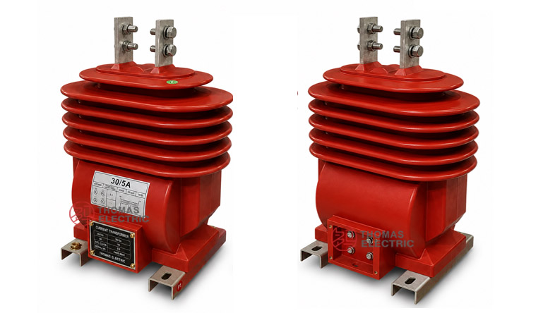
The LZZB1-24W outdoor epoxy resin cast current transformer is a dry-type medium-voltage instrument transformer designed for 24kV outdoor distribution systems. It is used for current measurement, energy metering and relay protection in AC power systems with rated frequency of 50Hz or 60Hz. The product adopts an outdoor epoxy cast-resin fully enclosed structure, providing insulation strength and mechanical stability for exposed installation environments.
This model should be positioned separately from the LZZBW-15 / LZZBW-24 family. The LZZB1-24W is more focused on a compact outdoor 24kV single-platform CT with a clear terminal-box layout, approximately 39kg product weight, and 24/65/125kV insulation level. It is suitable for outdoor feeder metering, distribution transformer protection, pole-mounted equipment, and compact substation applications where an oil-free outdoor CT is preferred.
Product Type


| Item | Specification |
|---|---|
| Product name | Outdoor Epoxy Resin Cast Current Transformer |
| Model | LZZB1-24W |
| Installation condition | Outdoor |
| Structure | Outdoor dry-type epoxy resin cast structure |
| Application | Current measurement, energy metering and relay protection |
| Voltage class | 24kV medium-voltage distribution system |
| Rated insulation level | 24/65/125kV |
| Rated frequency | 50Hz or 60Hz |
| Rated secondary current | 5A or 1A |
| Approximate weight | About 39kg |
Model Explanation
- L: Current transformer.
- Z: Pillar-type / post-type current transformer structure.
- Z: Epoxy resin cast insulation.
- B: Metering and protection current transformer series.
- 1: Design sequence or structure platform code.
- 24: 24kV rated voltage class.
- W: Outdoor type.
- 5A or 1A: Rated secondary current option.
- Accuracy class: Metering classes such as 0.2S, 0.2, 0.5S, 0.5, and protection classes such as 5P or 10P according to project requirement.
Product Positioning
The LZZB1-24W should be written as a 24kV outdoor dry-type epoxy CT for compact distribution metering and protection. Compared with outdoor oil-immersed CTs, it eliminates transformer oil and reduces leakage-related maintenance. Compared with larger multi-voltage LZZBW platforms, it is more direct and focused: one 24kV outdoor epoxy CT platform, lighter structure, defined outline dimensions, and straightforward metering / protection class selection.
| Positioning Point | Technical Meaning | Website Expression |
|---|---|---|
| 24kV single platform | Dedicated 24kV outdoor CT design | Clear 24kV outdoor metering and protection CT page |
| Dry-type epoxy insulation | No transformer oil inside the CT body | Oil-free outdoor epoxy cast-resin insulation |
| Compact outdoor structure | Approx. 39kg weight and defined outline dimensions | Suitable for compact outdoor installations and distribution equipment |
| Metering + protection | Accuracy combinations include measurement and protection windings | Supports energy metering, current measurement and relay protection |
| Terminal-box access | Secondary terminals are arranged on the front lower terminal box | Convenient field wiring and maintenance inspection |
Applications
- 24kV outdoor medium-voltage distribution lines
- Outdoor feeder metering and energy measurement points
- Distribution transformer protection and current monitoring circuits
- Pole-mounted metering equipment and outdoor switching devices
- Compact substations and outdoor distribution cabinets
- Industrial outdoor power distribution and renewable energy grid connection systems
- Projects requiring an oil-free outdoor CT with epoxy resin insulation
Features
- Outdoor epoxy cast-resin body: Fully enclosed dry insulation structure for outdoor service conditions.
- 24/65/125kV insulation level: Suitable for 24kV class distribution systems and IEC-oriented project documentation.
- Oil-free construction: No transformer oil, reducing leakage risk and simplifying field maintenance.
- Metering and protection accuracy: Supports 0.2S / 0.2 / 0.5S / 0.5 metering classes and 5P protection classes according to project selection.
- Compact outline and weight: Approximate product weight of 39kg supports outdoor brackets, compact substation layouts and field installation.
- Accessible secondary terminal box: Front terminal box layout supports secondary cable connection, testing and maintenance access.
Operating Principle
The LZZB1-24W current transformer converts the primary current of a 24kV circuit into a standardized secondary current signal, normally 5A or 1A. The secondary output is connected to meters, protection relays or monitoring equipment, allowing safe measurement and protection without direct connection to the high-voltage primary circuit.
For energy metering, the selected metering core must maintain the required ratio accuracy and phase displacement within the specified burden. For relay protection, the protection core must provide dependable secondary output under fault-current conditions. Therefore, the rated primary current, accuracy class combination, rated output, short-time thermal current and dynamic current must be confirmed together before production.
Technical Data
| Parameter | Specification |
|---|---|
| Model | LZZB1-24W |
| Product type | Outdoor epoxy resin cast current transformer |
| Rated voltage class | 24kV |
| Rated insulation level | 24/65/125kV |
| Rated frequency | 50Hz or 60Hz |
| Rated secondary current | 5A or 1A |
| Rated primary current | 20A to 2500A reference range according to supplied catalogue data |
| Accuracy class combination | 0.2S/0.5, 0.2/0.5, 0.2/5P10, 0.5/5P10, 0.2S/5P20 and related combinations |
| Rated output | 10VA, 15VA, 20VA depending on current ratio and accuracy class |
| Ambient temperature | -5°C to +40°C reference from catalogue data |
| Approximate weight | About 39kg |
| Applicable standards | IEC 61869-1, IEC 61869-2, GB/T 20840.1, GB/T 20840.2; project-specific requirements by agreement |
Selection Table
The following table is reorganized from the supplied catalogue data and optimized for website display. Long table headings and accuracy class cells are split into multiple lines to avoid overflow on product pages.
| Rated
Primary |
Accuracy
Class |
Rated Output (VA) |
Short-Time ThermalCurrent |
Rated
Dynamic |
|---|---|---|---|---|
| 20–40 | 0.2S / 0.5 0.2 / 0.5 0.2 / 5P10 0.5 / 5P10 |
10 / 15 | 250 × I1n | 625 × I1n |
| 50–100 | 10 / 15 | 300 × I1n | 750 × I1n | |
| 150–250 | 10 / 15 | 40kA | 100kA | |
| 300–2500 | 15 / 20 | 63kA | 160kA | |
| 10–200 | 0.2S / 5P20 0.2 / 5P20 0.5S / 5P20 0.5 / 5P20 0.2S / 0.5 / 5P10 |
10 / 15 / 15 | 150 × I1n | 375 × I1n |
| 300–500 | 10 / 15 / 15 | 40kA | 100kA | |
| 600–1000 | 15 / 20 / 20 | 80kA | 200kA |
Note: The table is for preliminary selection. Final ratio, rated burden, accuracy class, short-time thermal current, dynamic current and terminal arrangement shall be confirmed according to the nameplate, approved drawing and factory test report.
Normal Operating Conditions
| Parameter | Value |
|---|---|
| Installation place | Outdoor |
| Maximum ambient temperature | +40°C reference |
| Minimum ambient temperature | -5°C reference from catalogue data; lower temperature available by agreement |
| Rated frequency | 50Hz or 60Hz |
| Altitude | ≤ 1000m under standard service conditions; higher altitude by agreement |
| Atmospheric condition | No severe pollution, corrosive gas or explosive atmosphere beyond design limits |
| Outdoor exposure | Suitable for outdoor humidity, UV exposure and tracking-resistant insulation applications |
Installation and Dimensions

The LZZB1-24W is installed outdoors on a stable mounting plate, pole-mounted support, steel bracket or substation structure. The bottom mounting feet should be fixed securely before primary conductor connection. The secondary terminal box is located at the lower front side, allowing accessible secondary wiring, testing and inspection.
| Dimension / Installation Item | Reference Value / Recommended Check Point |
|---|---|
| Overall height | Approx. 481 ± 5mm reference from drawing |
| Front width | Approx. 344mm maximum reference; 286mm / 264mm body references |
| Side width | Approx. 238mm reference |
| Base depth | Approx. 196mm reference |
| Terminal spacing | Top primary terminal spacing approx. 78mm reference |
| Primary terminals | Top P1 / P2 terminal arrangement |
| Secondary terminal box | Front lower terminal box for secondary wiring |
| Approximate weight | About 39kg |
| Mounting check | Confirm base hole spacing, bracket strength, conductor direction, grounding and cable outlet before installation. |
Windings & Terminal Marking
The primary terminals are marked P1 and P2. The secondary terminals are arranged inside the front terminal box and should be connected according to the approved wiring diagram. For combined metering and protection configurations, each secondary winding must be assigned to a specific function before production.
| Terminal | Function | Application Note |
|---|---|---|
| P1 / P2 | Primary terminals | Used for primary current direction and polarity reference. |
| S1 / S2 | Single secondary winding | Used when one secondary output is specified. |
| 1S1 / 1S2 | First secondary winding | Usually assigned to metering or current measurement. |
| 2S1 / 2S2 | Second secondary winding | Usually assigned to relay protection. |
| 3S1 / 3S2 | Additional secondary winding when specified | Used for backup protection or independent monitoring circuit. |
| Grounding point | Secondary / base grounding reference | One point of the secondary circuit and the CT base should be grounded according to project practice. |
Standards and Compliance
For current international documentation, the LZZB1-24W should be specified according to IEC 61869-1 and IEC 61869-2. For GB-based documentation, GB/T 20840.1 and GB/T 20840.2 can be used. The supplied catalogue references GB20840.2-2014 and IEC 61869-2:2012 as the product standard basis. Final compliance scope should be confirmed according to the order, routine test plan and project technical agreement.
Safety Notes
- Confirm voltage class, rated insulation level, current ratio, secondary current, accuracy class and rated output before installation.
- Check P1 / P2 polarity and secondary terminal marking before wiring meters, relays or test devices.
- Confirm base mounting strength, bracket stability, conductor connection direction and required electrical clearance.
- Ground the CT base and one point of the secondary circuit according to the station grounding design.
- The CT secondary circuit must not be open-circuited while primary current is flowing.
- Before disconnecting meters or relays, short-circuit the secondary circuit with an approved shorting device.
- Seal the terminal box after wiring to reduce moisture ingress and maintain outdoor reliability.
- Installation and commissioning shall be performed by qualified medium-voltage electrical personnel.
Ordering Info
| Item | Options / Examples |
|---|---|
| Model | LZZB1-24W |
| Rated voltage class | 24kV |
| Rated insulation level | 24/65/125kV |
| Rated primary current | 20A, 50A, 100A, 200A, 400A, 600A, 1000A or customized |
| Rated secondary current | 5A or 1A |
| Accuracy class and burden | 0.2S/0.5, 0.2/5P10, 0.5/5P20, 10/15VA, 15/20VA, etc. |
| Application | Metering, measurement, protection or multi-secondary output |
| Installation environment | Altitude, pollution level, UV exposure, humidity and special outdoor conditions |
| Documentation | Drawing, wiring diagram, routine test report, certificate, label language and packing requirement |