Product Overview
The LZZ(B)J2-10 / LZZBJ2-12 Indoor Post-Type current transformer is an indoor epoxy cast-resin, full-enclosed, support-type single-phase current transformer for medium-voltage AC systems. It is designed for current measurement, energy metering, feeder monitoring, and relay protection in 10kV, 11kV and 12kV class indoor switchgear.
The product uses an epoxy resin cast insulation body with a Post-Type compact support structure. The primary terminals are arranged on the upper side, while the secondary terminal group is positioned on the lower side for convenient switchgear wiring. The product is suitable for single-ratio or double-ratio configurations, with 5A or 1A secondary output and metering/protection core combinations according to project requirements.
For international product pages, this series should be presented as a 12kV class indoor current transformer. The older catalogue designation may show LZZ(B)J2-10, while project and export pages can use LZZBJ2-12 when the insulation level, standards, mounting dimensions, and nameplate requirements are confirmed.
Product Type
| Item | Specification |
|---|---|
| Product name | Indoor Post-Type Epoxy Cast-Resin Current Transformer |
| Model series | LZZ(B)J2-10 / LZZBJ2-12 |
| Structure | Indoor, Post-Type, full-enclosed, support-type, single-phase current transformer |
| Voltage class | 10kV, 11kV and 12kV class medium-voltage systems |
| Rated insulation | 12/42/75kV |
| Rated frequency | 50Hz |
| Secondary current | 5A or 1A |
| Winding form | Single-ratio or double-ratio secondary configuration |
| Installation | Indoor busbar / support-type switchgear installation |
| Applications | Protection, measurement, energy metering, feeder monitoring |
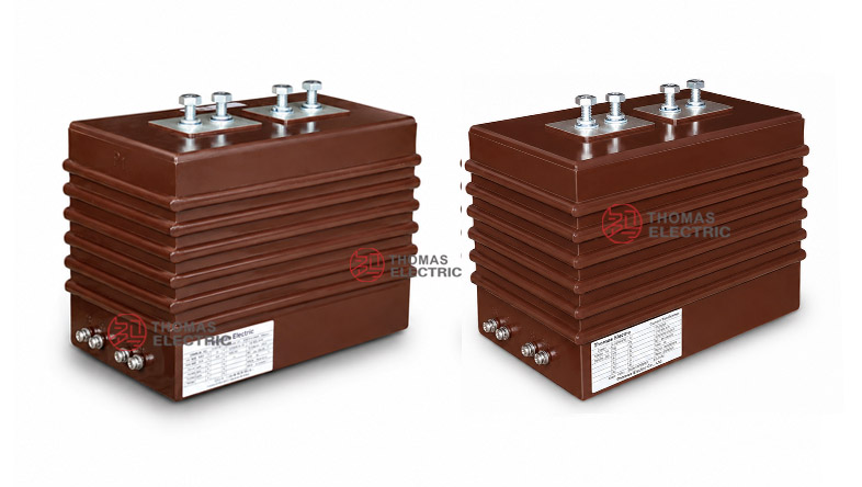
Product Display
J2-10, LZZBJ2-12 Post-Type Epoxy Cast-Resin Current Transformer Thomas Electric")
J2-10, LZZBJ2-12 Post-Type Epoxy Cast-Resin Current Transformer Thomas Electric")
Applications
- 10kV, 11kV and 12kV class indoor Post-Type medium-voltage distribution systems
- Metal-clad switchgear, feeder cabinets, incoming panels and outgoing panels
- Current measurement and electric energy metering circuits
- Relay protection circuits for feeders, transformers, motors and distribution lines
- SCADA, power monitoring and distribution automation systems
- Single-ratio and double-ratio switchgear projects requiring flexible CT selection
Features
- Full-enclosed resin body: The epoxy resin cast structure provides insulation strength, mechanical protection and stable indoor service performance.
- 12kV insulation class: The 12/42/75kV insulation level makes the product suitable for international 10kV, 11kV and 12kV class systems.
- Single and double ratio options: The product supports single-ratio and double-ratio configurations for different measurement and protection schemes.
- Metering and protection cores: Accuracy combinations such as 0.2/10P10, 0.5/10P10 and multi-core combinations are available according to project requirements.
- 5A or 1A secondary output: Secondary current can be selected according to meter, relay, cable length and burden requirements.
- Compact support structure: Suitable for indoor busbar-type installation in medium-voltage switchgear with defined mounting dimensions.
Principle
The LZZ(B)J2-10 / LZZBJ2-12 Post-Type current transformer operates by electromagnetic induction. The primary current flowing through the primary terminal path generates magnetic flux in the core. The secondary winding then outputs a proportional current signal to the connected meter, relay or monitoring device. The epoxy resin insulation separates the primary medium-voltage circuit from the secondary low-voltage circuit.
For metering, the selected core must maintain ratio accuracy and phase displacement within the specified burden. For protection, the 10P core must provide a reliable secondary current signal under fault-current conditions and coordinate with relay settings.
Model Designation
The model code can be interpreted as follows:
| Code | Meaning |
|---|---|
| L | Current transformer |
| Z | Indoor type |
| Z | Epoxy resin cast insulation / fully enclosed Post-Type structure |
| B | Protection class available |
| J | Reinforced / enhanced design |
| 2 | Design sequence code |
| 10 / 12 | 10kV catalogue code / 12kV international insulation class |
Technical Data
| Item | Specification |
|---|---|
| Rated voltage class | 10kV, 11kV and 12kV class indoor systems |
| Rated insulation | 12/42/75kV |
| Rated frequency | 50Hz |
| Rated primary current | 20A to 1000A reference range, subject to single-ratio or double-ratio configuration |
| Rated secondary current | 5A or 1A |
| Accuracy combination | 0.2/10P10, 0.2/0.2, 0.5/10P10, 10P10/10P10, 0.5/0.5, 0.5/0.5/10P10, 0.2/0.5/10P10 |
| Rated output | 10VA, 15VA, 20VA or 25VA depending on current ratio and core configuration |
| Ambient temperature | -5°C to +55°C |
| Phase | Single phase |
| Insulating medium | Epoxy resin |
| Applicable standards | GB1208-2006, IEC 60044-1:2003 and special project requirements |
Terminals
The current transformer can be supplied with single-ratio or double-ratio secondary terminal arrangements. Typical secondary terminals are marked as 1S1 / 1S2, 2S1 / 2S2 and 2S3 according to the winding and tapping arrangement shown on the approved drawing.
| Terminal
Marking |
Function | Application
Note |
|---|---|---|
| P1 / P2 | Primary terminals | Primary current direction and busbar connection shall follow the drawing and wiring diagram. |
| 1S1 / 1S2 | First secondary winding | Usually used for metering, measurement or the first specified secondary core. |
| 2S1 / 2S2 | Second secondary winding | Used for protection or an additional measuring circuit according to core configuration. |
| 2S3 | Secondary tap | Used when a double-ratio or tapped secondary configuration is specified. |
Single Ratio
The following selection reference is for single-ratio configurations. Shared accuracy combinations and rated outputs are grouped to reduce repeated data and keep the table readable on responsive website layouts.
| Rated
Primary Current (A) |
Accuracy
Class Combination |
Rated
Output (VA) |
Short-Time
Thermal Current (kA) |
Dynamic
Current (kA) |
Remark |
|---|---|---|---|---|---|
| 20 | 0.2 / 10P10 0.2 / 0.2 0.5 / 10P10 10P10 / 10P10 0.5 / 0.5 0.5 / 0.5 / 10P10 0.2 / 0.5 / 10P10 |
0.2: 10 0.5: 10 10P10: 15 |
1.6 / 2 | 4 | Single ratio |
| 30–40 | 3.15 / 2 | 8 | |||
| 50 | 6.3 / 2 | 16 | |||
| 75 | |||||
| 100–150 | 8 / 2 | 20 | |||
| 200 | 12.5 / 2 | 31.5 | |||
| 300 | 20 / 2 | 50 | |||
| 400 | |||||
| 500–600 | 0.2: 15 0.5: 15 10P10: 20 |
25 / 4 | 63 | ||
| 800 | 31.5 / 4 | 80 | |||
| 1000 | 0.2: 20 0.5: 20 10P10: 25 |
Double Ratio
The following selection reference is for double-ratio configurations. Final tap arrangement, secondary marking and ratio combination shall be confirmed according to the project drawing and nameplate.
| Rated
Primary Current (A) |
Accuracy
Class Combination |
Rated
Output (VA) |
Short-Time
Thermal Current (kA) |
Rated
Dynamic Current (kA) |
Remark |
|---|---|---|---|---|---|
| 20–30 | 0.2 / 10P10 0.5 / 10P10 10P10 / 10P10 |
0.2: 10 0.5: 10 10P10: 15 |
1.2 / 2 | 4 | Double ratio |
| 30–40 | 3.15 / 2 | 8 | |||
| 40–50 | |||||
| 50–75 | 6.3 / 2 | 16 | |||
| 75–100 | |||||
| 100–150 | 8 / 2 | 20 | |||
| 150–200 | 12.5 / 4 | 31.5 | |||
| 200–300 | 20 / 4 | 50 | |||
| 300–400 | |||||
| 400–600 | 0.2: 15 0.5: 15 10P10: 20 |
25 / 4 | 63 | ||
| 600–800 | 31.5 / 4 | 80 | |||
| 800–1000 | 0.2: 20 0.5: 20 10P10: 25 |
Note: If the user data exceeds the above mentioned scopes, they may be subject to an agreement between manufacturer and purchaser. Final current ratio, burden, accuracy, Ith, Idyn and terminal marking shall be confirmed according to the nameplate, approved drawing and factory test report.
Service Conditions
- Installation location: indoor medium-voltage switchgear
- System voltage: 10kV, 11kV and 12kV class networks
- Rated frequency: 50Hz
- Ambient temperature: -5°C to +55°C
- The installation environment should be free from severe vibration, conductive dust, corrosive gas, explosive medium, heavy pollution and abnormal condensation.
- For high altitude, humid, coastal or special switchgear applications, technical confirmation is required before ordering.
Standards and Compliance
The LZZ(B)J2-10 / LZZBJ2-12 current transformer conforms to GB1208-2006, IEC 60044-1:2003 and special project requirements. For international projects, IEC 61869-1 and IEC 61869-2 can also be used as reference standards when required by the technical agreement. Routine tests typically include ratio test, polarity verification, accuracy test, insulation withstand test and appearance inspection.
Installation and Dimensions
J2-10, LZZBJ2-12 Post-Type Epoxy Cast-Resin Current Transformer Thomas Electric")
The product adopts a compact support-type structure for indoor switchgear installation. The catalogue reference shows an overall width of approximately 286mm, base mounting length around 220mm, and mounting hole arrangements including 4-M10. Primary terminal arrangements differ according to current range, and final installation dimensions shall be confirmed by approved drawing before cabinet production.
Dimensions
| Item | Dimension / Note |
|---|---|
| Overall width | 286mm reference |
| Base mounting length | 220mm reference |
| Overall mounting width | 273 ± 2mm reference |
| Side mounting width | 160 ± 2mm reference |
| Mounting holes | 4-M10 reference |
| Terminal arrangement | Different primary terminal layouts for I1n ≤ 1000A and 1200A ≤ I1n ≤ 2000A |
| Weight | Approximately 25.5kg |
Safety Notes
- Confirm the model, current ratio, secondary current, accuracy combination, rated output and insulation level before installation.
- Check the switchgear mounting space, busbar connection, terminal layout and phase clearance before cabinet assembly.
- Connect P1/P2 and secondary terminals according to polarity markings and the project wiring diagram.
- The secondary circuit of a current transformer must not be open-circuited when the primary circuit is energized.
- Before disconnecting meters or relays, short-circuit the secondary circuit through an approved shorting terminal block.
- One point of the secondary circuit should be grounded according to project requirements and local electrical safety regulations.
- Installation and maintenance shall be performed by qualified medium-voltage electrical personnel.
Ordering Info
Please provide the following information when ordering or requesting a quotation:
- Product model: LZZ(B)J2-10 or LZZBJ2-12
- Single ratio or double ratio configuration
- Rated primary current and rated secondary current
- Accuracy class combination and rated output
- Rated insulation level and applicable standard
- Required short-time thermal current and dynamic current
- Terminal marking, tap arrangement and wiring diagram requirement
- Switchgear layout, mounting dimension and primary terminal direction
- Quantity, certificates, routine test reports, labeling and packaging requirements
Selection Guide
- Confirm voltage class: Use this CT for indoor 10kV, 11kV and 12kV class systems with 12/42/75kV insulation level.
- Confirm ratio type: Select single ratio for fixed operating ranges or double ratio where two primary ranges are required.
- Select primary current: Choose the rated primary current according to feeder load and protection setting range.
- Define core functions: Specify metering and protection cores separately, including accuracy class and rated output.
- Check secondary burden: Confirm that meter, relay and cable burden do not exceed the rated output of each secondary core.
- Verify fault rating: Rated short-time thermal current and rated dynamic current shall match the switchgear fault level.
- Confirm dimensions: Check mounting holes, primary terminal layout, secondary terminals and cabinet clearance before production.