Product Overview
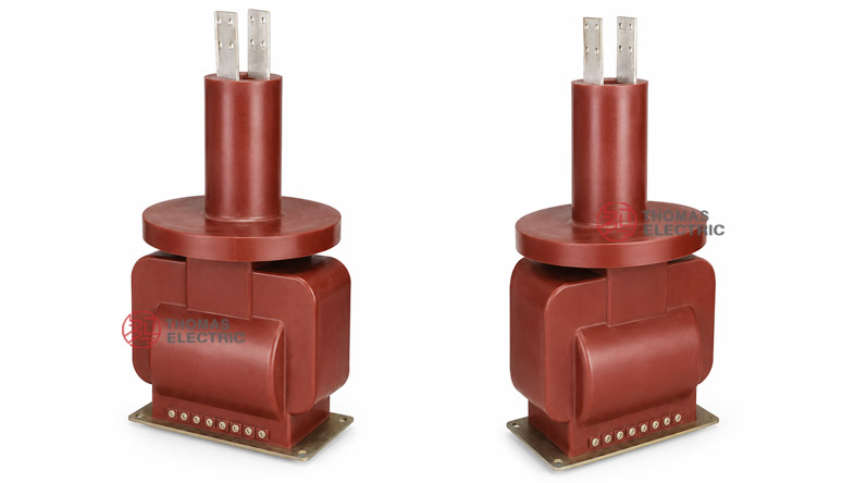
The LZZBJ4-35 support-type epoxy resin cast current transformer is a fully enclosed indoor medium-voltage current transformer designed for 35kV and 40.5kV power systems. It is used for current measurement, energy metering and relay protection in AC networks with rated frequency of 50Hz or 60Hz. The product adopts electrical-grade epoxy resin casting insulation, with the primary winding, secondary winding and annular magnetic core sealed inside the resin body to form a compact, high-strength and maintenance-friendly insulation structure.
This product should be positioned differently from outdoor epoxy CTs such as LZZB1-35W, LZZBJ71-35 or LZZBW1-35Q. The LZZBJ4-35 is mainly an indoor support-type hermetically cast CT for switchgear, vacuum circuit breaker cabinets and medium-voltage distribution equipment. Its value is in compact structure, low partial discharge, stable accuracy under temperature variation, reinforced magnetic core design, and protection accuracy suitable for relay circuits. For international product pages, it can be written for 35kV / 40.5kV class systems with a rated insulation level of 40.5/95/185kV.
Product Type


| Item | Specification |
|---|---|
| Product name | Support Type Hermetically Cast Insulation Current Transformer |
| Model | LZZBJ4-35 |
| Installation condition | Indoor |
| Structure | Support-type, fully enclosed epoxy cast-resin structure |
| Insulation type | Epoxy resin cast insulation |
| Application | Current measurement, energy metering and relay protection |
| System voltage class | 35kV / 40.5kV |
| Rated insulation level | 40.5/95/185kV |
| Rated frequency | 50Hz or 60Hz |
| Rated secondary current | 5A or 1A |
| Typical installation | Indoor switchgear, vacuum circuit breaker cabinet, ZW35 breaker system and distribution cabinet |
Model Explanation

- L: Current transformer.
- Z: Support-type / pillar-type structure.
- Z: Epoxy resin casting insulation.
- B: Current transformer with protection-class configuration option.
- J: Reinforced type / enhanced structure design.
- 4: Design sequence number.
- 35: 35kV class product platform, suitable for 35kV and 40.5kV systems.
Applications
- 35kV and 40.5kV indoor power distribution systems
- Medium-voltage switchgear and circuit breaker cabinets
- ZW35 vacuum circuit breaker and similar indoor distribution equipment
- Current measurement and energy metering circuits
- Relay protection for incoming and outgoing feeders
- Industrial substations and utility distribution rooms
- Projects requiring compact epoxy cast-resin CTs with both measurement and protection functions
Features
- Support-type fully enclosed structure: The CT adopts a compact post-type design with epoxy resin casting insulation.
- 40.5/95/185kV insulation level: Suitable for 35kV / 40.5kV class indoor medium-voltage systems.
- Hermetically cast epoxy body: Primary winding, secondary winding and magnetic core are sealed inside the resin body for stable insulation performance.
- High-quality magnetic core: The measuring core uses high-permeability, low-coercivity and low-loss magnetic material for improved measurement stability.
- Protection-class design: Protection-grade cores can be configured to meet relay protection requirements such as Fs <= 10 or related protection accuracy conditions.
- Low partial discharge: Cast-resin insulation and optimized structure help reduce partial discharge risk in medium-voltage operation.
- Temperature stability: Accuracy performance is designed to remain within the required range under normal ambient temperature changes.
- Switchgear-friendly installation: Fixed as a whole with the upper flange and supported at the lower base plate with bolts.
Operating Principle
The LZZBJ4-35 current transformer converts the primary current in a 35kV / 40.5kV circuit into a standardized secondary current signal, usually 5A or 1A. The secondary signal is connected to meters, protection relays or monitoring devices, allowing safe measurement and protection without direct connection to the high-voltage primary circuit.
For measurement and energy metering, the CT must maintain ratio accuracy and phase displacement within the selected burden. For relay protection, the protection winding must provide reliable secondary output under fault-current conditions. Therefore, current ratio, rated burden, accuracy class, safety factor and short-time withstand current should be selected together according to the switchgear system design.
Technical Data
| Parameter | Specification |
|---|---|
| Model | LZZBJ4-35 |
| Product type | Indoor support-type epoxy resin cast current transformer |
| System voltage class | 35kV / 40.5kV |
| Rated insulation level | 40.5/95/185kV |
| Rated frequency | 50Hz or 60Hz |
| Rated secondary current | 5A or 1A |
| Load power factor | cos phi = 0.8 lag reference |
| Safety factor | Fs <= 10 reference for metering protection coordination |
| Altitude | Not more than 2000m reference |
| Applicable standard | IEC 61869-1, IEC 61869-2, GB/T 20840.1, GB/T 20840.2; legacy GB20840.2-2014 reference |
| Typical function | Current measurement, energy metering and relay protection |
Selection Table
The following selection table is optimized for website use. Long table headings are split into multiple lines to reduce layout overflow on product pages.
| Rated
Primary |
Accuracy
Class |
Rated
Output |
Short-Time ThermalCurrent |
Rated
Dynamic |
|---|---|---|---|---|
| 50 | 0.2 / 0.2 0.2 / 0.5 0.5 / 0.5 0.2 / 0.5 / 10P10 0.2 / 0.5 / 10P15 10P10 / 10P10 10P15 / 10P15 |
0.2: 15VA 0.5: 25VA 10P10: 50VA |
3kA | 7.5kA |
| 75 | 0.2: 15VA 0.5: 25VA 10P10: 50VA |
5kA | 12.5kA | |
| 100 | 0.2: 15VA 0.5: 25VA 10P10: 50VA |
8kA | 20kA | |
| 31.5 | 0.2: 15VA 0.5: 25VA 10P10: 50VA |
12kA | 30kA | |
| 200 | 0.2: 15VA 0.5: 25VA 10P10: 50VA |
16kA | 40kA | |
| 300, 400 | 0.2 / 0.2 / 10P10 0.2 / 0.5 / 10P10 0.5 / 0.5 / 10P10 0.2 / 10P10 / 10P10 10P10 / 10P10 / 10P10 10P10 / 10P10 / 10P10 / 10P10 |
0.2: 15VA 0.5: 25VA 10P10: 50VA |
20kA | 50kA |
| 600 | 0.2: 15VA 0.5: 25VA 10P10: 50VA |
31.5kA | 80kA | |
| 800, 1000, 1200, 1500, 1600 | 0.2: 15VA 0.5: 25VA 10P10: 50VA |
40kA | 100kA |
Note: The table is for preliminary selection. If the required data is beyond the above scope, it can be confirmed by technical agreement between manufacturer and purchaser. Final values shall follow the nameplate, approved drawing and factory test report.
Operating Conditions
- Installation: Indoor installation for 35kV / 40.5kV switchgear and distribution systems.
- Rated frequency: 50Hz or 60Hz.
- Altitude: Not more than 2000m reference.
- Ambient environment: No severe pollution, corrosive gas, explosive atmosphere or abnormal vibration beyond product design limits.
- Service equipment: Suitable for indoor switchgear, vacuum circuit breaker cabinet and related medium-voltage distribution equipment.
- Insulation condition: Keep the resin surface clean and dry; avoid conductive dust accumulation and condensation during operation.
Installation and Dimensions

The LZZBJ4-35 is normally installed inside medium-voltage switchgear or circuit breaker equipment. The product is fixed as a whole with the upper flange, and the lower part is supported by the base plate with four M10 bolts. Before installation, confirm the mounting dimensions, top terminal arrangement, conductor clearance, secondary terminal position and cabinet insulation distance according to the approved drawing.
Dimension Notes
| Dimension Item | Reference Value / Note |
|---|---|
| Overall height | Approx. 798 +/- 5mm reference from supplied drawing |
| Top terminal spacing | Approx. 80mm / 40mm reference depending on terminal view |
| Body lower width | Approx. 385mm reference |
| Base reference diameter | Approx. 370mm / 330mm reference |
| Base width | Approx. 400mm reference |
| Mounting hole | 12 x 13mm reference from drawing |
| Terminal detail | Top terminal and secondary terminal layout shall follow the approved project drawing. |
Windings & Marking
The high-voltage primary terminals are arranged at the top of the product. Secondary terminals are connected according to the approved terminal diagram. For multi-core configurations, each secondary winding group must be identified clearly for metering, measurement or protection use.
| Terminal | Function | Application Note |
|---|---|---|
| P1 / P2 | Primary terminals | Used for primary current direction and polarity reference. |
| S1 / S2 | Single secondary winding | Used when one secondary output is specified. |
| 1S1 / 1S2 | First secondary winding | Usually assigned to metering or current measurement. |
| 2S1 / 2S2 | Second secondary winding | Usually assigned to relay protection. |
| 3S1 / 3S2 | Additional secondary winding when specified | Used for backup protection or independent measurement circuit. |
| Grounding point | Secondary / equipment grounding reference | One point of the secondary circuit should be grounded according to project practice. |
Standards and Compliance
For updated international documentation, the LZZBJ4-35 should be specified according to IEC 61869-1 and IEC 61869-2. For GB-based documentation, GB/T 20840.1 and GB/T 20840.2 can be used. Legacy references such as IEC185 or earlier CT standards may appear in older catalogues, but modern product pages should use IEC 61869 and GB/T 20840 series as the preferred standard language.
Safety Notes
- Confirm voltage class, rated insulation level, current ratio, secondary current, accuracy class and rated output before installation.
- Check that the selected CT matches the switchgear insulation distance and the system short-circuit level.
- Verify P1 / P2 polarity and secondary terminal marking before connecting meters, relays or test equipment.
- Ensure the CT is fixed firmly with the required bolts and cabinet support structure.
- Ground one point of the secondary circuit according to the switchgear grounding design.
- The CT secondary circuit must not be open-circuited while primary current is flowing.
- Before disconnecting meters, relays or test devices, short-circuit the secondary circuit with an approved shorting device.
- Keep the epoxy resin surface clean and dry to reduce tracking and insulation risk.
- Do not use the CT in environments with severe condensation, corrosive gas, explosive atmosphere or abnormal vibration beyond design limits.
- Installation, testing and commissioning shall be performed by qualified medium-voltage electrical personnel.