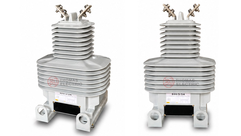
Product Overview
The LZZBJ71-35 / LZZBJ71-35W GY outdoor epoxy resin cast current transformer is a fully enclosed, pillar-type outdoor current transformer designed for 33kV, 35kV and 40.5kV power systems. It is used for current measurement, energy metering and relay protection in outdoor AC networks with rated frequency of 50Hz or 60Hz. The product adopts outdoor-grade epoxy resin casting insulation, sealing the primary winding, secondary winding and magnetic core inside the resin body to provide high mechanical strength, stable insulation performance and reliable outdoor service capability.
This series is positioned as a 35kV-class outdoor dry-type current transformer for utility feeders, outdoor substations, renewable energy collection lines, pole-mounted metering equipment and industrial distribution systems. Compared with oil-immersed outdoor CTs, it is oil-free, cleaner for field operation and easier to maintain. Compared with compact 24kV outdoor epoxy CTs, this product is designed for a higher insulation platform of 40.5/95/185kV, with stronger outdoor creepage performance, improved overvoltage withstand capability and metering / protection winding combinations for medium-voltage distribution projects. The LZZBJ71-35 can be used as the standard outdoor 35kV epoxy CT platform, while LZZBJ71-35W GY can be positioned as the outdoor reinforced / project-variant version for specified installation, terminal or insulation requirements.
Product Type


| Item | Specification |
|---|---|
| Product name | Outdoor Epoxy Resin Cast Current Transformer |
| Model | LZZBJ71-35 / LZZBJ71-35W GY |
| Installation condition | Outdoor |
| Structure | Fully enclosed pillar-type / post-type structure |
| Insulation type | Outdoor epoxy resin cast insulation |
| Application | Current measurement, energy metering and relay protection |
| System voltage class | 33kV / 35kV / 40.5kV |
| Rated insulation level | 40.5/95/185kV |
| Rated frequency | 50Hz or 60Hz |
| Rated secondary current | 5A or 1A |
| Typical structure | Top primary terminals with lower front secondary terminal box |
Model Explanation

- L: Current transformer.
- Z: Pillar-type / post-type current transformer structure.
- Z: Epoxy resin cast insulation.
- B: Current transformer series with metering and protection winding options.
- J: Reinforced insulation / enhanced design reference.
- 71: Design sequence / structural platform code.
- 35: 35kV class product platform, suitable for 33kV, 35kV and 40.5kV systems.
- W: Outdoor type.
- GY: Project-specific structural variant, often used for reinforced outdoor configuration, special terminal arrangement or installation requirement.
Operating Conditions
- Installation: Outdoor installation for 33kV / 35kV / 40.5kV power systems.
- Ambient temperature: -5°C to +40°C reference; wider temperature range can be confirmed by agreement.
- Rated frequency: 50Hz or 60Hz.
- Altitude: Standard service altitude according to project specification; high-altitude applications require insulation correction.
- Site environment: No severe corrosive gas, explosive atmosphere or abnormal mechanical impact beyond product design limits.
- Outdoor exposure: Suitable for UV exposure, humidity, tracking resistance and outdoor insulation coordination requirements.
- Pollution condition: Pollution level and creepage distance should be confirmed according to project location and grid standard.
Applications
- 33kV, 35kV and 40.5kV outdoor distribution networks
- Outdoor substations and utility feeder metering points
- Current measurement for incoming and outgoing distribution feeders
- Energy metering for utility, industrial and commercial power supply systems
- Relay protection for overhead lines, transformers and feeder circuits
- Outdoor switchgear, pole-mounted metering equipment and compact substations
- Renewable energy grid connection systems, including solar and wind farm collection lines
- Projects requiring an oil-free outdoor CT with epoxy resin insulation and high insulation coordination
Features
- 35kV-class outdoor platform: Suitable for 33kV, 35kV and 40.5kV international voltage levels.
- 40.5/95/185kV insulation level: Designed for higher insulation coordination in outdoor medium-voltage networks.
- Oil-free epoxy cast-resin insulation: No transformer oil, reducing leakage risk and simplifying outdoor maintenance.
- Fully enclosed structure: Primary winding, secondary winding and core are sealed in the epoxy resin casting body.
- Outdoor terminal layout: Top P1 / P2 primary terminals and lower terminal box support field wiring and maintenance inspection.
- Metering and protection combinations: Supports energy metering, current measurement and relay protection in one CT platform.
- High mechanical strength: The cast-resin body supports outdoor installation, vibration resistance and long-term dimensional stability.
- Weather-resistant insulation: Suitable for UV exposure, humidity, aging resistance and outdoor pollution service conditions.
Operating Principle
The LZZBJ71-35 / LZZBJ71-35W GY current transformer converts high primary current in a 33kV / 35kV / 40.5kV circuit into a standardized secondary current signal, normally 5A or 1A. The secondary signal is supplied to measuring instruments, energy meters, protection relays or monitoring systems. This allows safe measurement and protection while keeping the secondary circuit isolated from the high-voltage primary circuit.
For metering applications, the CT must maintain ratio accuracy and phase displacement within the rated burden. For protection applications, the protection winding must provide reliable output under system fault-current conditions. Therefore, the rated primary current, rated secondary current, accuracy combination, rated output, short-time thermal current and dynamic current must be selected together according to the actual load current and short-circuit level of the installation point.
Technical Data
| Parameter | Specification |
|---|---|
| Model | LZZBJ71-35 / LZZBJ71-35W GY |
| Product type | Outdoor epoxy resin cast current transformer |
| System voltage class | 33kV / 35kV / 40.5kV |
| Rated insulation level | 40.5/95/185kV |
| Rated frequency | 50Hz or 60Hz |
| Rated secondary current | 5A or 1A |
| Rated primary current | 15A to 1000A reference range according to supplied catalogue data; extended range by technical agreement |
| Accuracy class combination | 0.2S/0.5, 0.2/0.5/10P10, 0.2/0.5/10P15, 10P10/10P10, 10P15/10P15, 0.2S/0.5/10P20/10P20 and related project combinations |
| Rated output | 20VA, 30VA, 50VA and multi-winding combinations depending on ratio and accuracy class |
| Rated short-time thermal current | 3kA to 80kA reference range according to ratio and catalogue data |
| Rated dynamic current | 7.5kA to 200kA reference range according to ratio and catalogue data |
| Ambient temperature | -5°C to +40°C reference; special outdoor service by agreement |
| Applicable standards | IEC 61869-1, IEC 61869-2, GB/T 20840.1, GB/T 20840.2; project-specific requirements by agreement |
Selection Table
The following selection table is reorganized from the supplied catalogue information and optimized for website display. Long headings and accuracy-class cells are split into multiple lines to reduce layout overflow on product pages.
| Rated Primary Current (A) |
Accuracy Class Combination |
Rated Output (VA) |
Rated Short-Time Thermal Current |
Rated Dynamic Current |
|---|---|---|---|---|
| 15 | 0.2S / 0.5 0.2 / 0.5 / 10P10 0.2 / 0.5 / 10P15 10P10 / 10P10 10P15 / 10P15 0.2S / 0.5 / 10P20 / 10P20 |
30 / 50 30 / 50 30 / 20 50 / 50 20 / 20 / 20 |
3kA | 7.5kA |
| 20 | 4kA | 10kA | ||
| 30 | 6kA | 15kA | ||
| 40 | 8kA | 20kA | ||
| 50 | 10kA | 25kA | ||
| 75 | 15kA | 37.5kA | ||
| 100 | 21kA | 52.5kA | ||
| 150 | 31.5kA | 78.75kA | ||
| 200 | 0.2S / 0.5 0.2 / 0.5 / 10P10 0.2 / 0.5 / 10P15 0.2 / 0.5 / 10P20 10P10 / 10P10 10P15 / 10P15 |
50 / 50 50 / 30 50 / 20 50 / 50 30 / 30 20 / 20 / 20 |
45kA | 112.5kA |
| 300 | 63kA | 157.5kA | ||
| 400 | 63kA | 157.5kA | ||
| 500–800 | 63kA | 157.5kA | ||
| 1000 | 80kA | 200kA |
Note: The table is for preliminary selection. If the required data is beyond the above range, it can be confirmed by technical agreement between manufacturer and purchaser. Final values shall follow the approved drawing, nameplate and factory test report.
Installation & Dimension

The LZZBJ71-35 / LZZBJ71-35W GY is installed outdoors on a stable steel bracket, pole-mounted support, mounting plate or substation foundation. The top primary terminals are used for P1 / P2 connection, while the lower front terminal box is used for secondary wiring. The base and mounting points must be checked against the approved drawing before installation.
| Installation Item | Recommended Check Point |
|---|---|
| Mounting base | Confirm base dimensions, mounting hole spacing, bracket strength and foundation stability. |
| Primary terminals | Check P1 / P2 direction, conductor connection method and phase-to-ground clearance. |
| Secondary terminal box | Reserve access space for cable entry, wiring, inspection, testing and sealing. |
| Grounding | Connect the CT base and one point of the secondary circuit to the station grounding system. |
| Outdoor clearance | Confirm creepage distance, pollution level, lightning impulse requirement and site insulation coordination. |
| Drawing confirmation | Use the approved outline drawing for the selected current ratio and terminal arrangement. |
Windings & Marking
The primary terminals are normally marked P1 and P2. The secondary terminals are arranged in the lower terminal box and should be wired according to the approved terminal diagram. For metering and protection combinations, each secondary winding group must be assigned clearly before production.
| Terminal | Function | Application Note |
|---|---|---|
| P1 / P2 | Primary terminals | Used for primary current direction and polarity reference. |
| S1 / S2 | Single secondary winding | Used when one secondary output is specified. |
| 1S1 / 1S2 | First secondary winding | Usually assigned to metering or current measurement. |
| 2S1 / 2S2 | Second secondary winding | Usually assigned to relay protection. |
| 3S1 / 3S2 | Additional secondary winding when specified | Used for backup protection, independent monitoring or special relay circuits. |
| Grounding point | Secondary / base grounding reference | One point of the secondary circuit and the CT base should be grounded according to project practice. |
Standards and Compliance
For updated international documentation, the LZZBJ71-35 / LZZBJ71-35W GY should be specified according to IEC 61869-1 and IEC 61869-2. GB-based documentation can refer to GB/T 20840.1 and GB/T 20840.2. Older catalogue references such as IEC 60044-1 can be retained only when required by a legacy tender or comparison document.
Safety Notes
- Confirm voltage class, rated insulation level, current ratio, secondary current, accuracy class and rated output before installation.
- Check that the selected CT matches the system fault level, including short-time thermal current and dynamic current requirements.
- Verify P1 / P2 polarity and secondary terminal marking before connecting meters, relays or test equipment.
- Ensure the outdoor mounting bracket is strong enough for the CT weight, conductor load and wind load at the installation site.
- Ground the CT base and one point of the secondary circuit according to the station grounding design.
- The CT secondary circuit must not be open-circuited while primary current is flowing.
- Before disconnecting meters, relays or test devices, short-circuit the secondary circuit with an approved shorting device.
- Seal the secondary terminal box after wiring to reduce moisture ingress and maintain outdoor reliability.
- Do not install the CT in an environment with severe chemical corrosion, explosive gas or abnormal vibration beyond the product design limits.
- Installation, testing and commissioning shall be performed by qualified medium-voltage electrical personnel.
Selection Guide
- Confirm voltage level: Use this series for 33kV, 35kV and 40.5kV outdoor systems.
- Select model variant: Use LZZBJ71-35 for the standard outdoor epoxy CT platform and LZZBJ71-35W GY for reinforced or project-specific outdoor configuration.
- Confirm insulation level: Use 40.5/95/185kV as the main insulation level for the 35kV-class platform.
- Select current ratio: Choose the primary current according to feeder load, metering range and protection setting.
- Choose secondary current: Use 5A for conventional meters and relays; use 1A for long secondary wiring or lower burden applications.
- Define accuracy class: Use 0.2S / 0.2 / 0.5 for metering and 10P / 5P classes for protection.
- Check rated output: Match CT burden with connected meters, relays, terminal blocks and secondary cable length.
- Check short-circuit withstand: Confirm Ith and Idyn according to the fault current level at the installation point.
- Approve drawings: Confirm outline drawing, terminal marking, mounting holes and secondary terminal box direction before production.