Product Overview
The LZZBJ9-10C2/180 and LZZBJ9-10C2Q/180/3 current transformers are indoor epoxy cast-resin, fully enclosed support-type current transformers built on the same C2/180 platform. This combined product page covers the standard C2/180 configuration and the C2Q/180/3 extended technical configuration for medium-voltage switchgear.
This platform is designed for 12 kV, 11 kV, 13.8 kV and 15 kV system applications, where compact support-type CT construction, stable epoxy insulation, reliable primary terminal connection and selectable secondary circuits are required. It is suitable for current measurement, energy metering, feeder monitoring, relay protection and automation input.
The C2/180 version is suitable for conventional metering and protection circuits. The C2Q/180/3 version provides deeper technical-table options for different accuracy combinations, secondary outputs and protection requirements. Combining both products into one page helps users compare the same 180 installation platform without splitting one product family into separate pages.
Product Type
| Item | Specification |
|---|---|
| Product name | Indoor Epoxy Cast-Resin Current Transformer |
| Model series | LZZBJ9-10C2/180 / LZZBJ9-10C2Q/180/3 |
| Structure | Indoor, fully enclosed, support-type, epoxy cast-resin insulated structure |
| System voltage application | 12 kV, 11 kV, 13.8 kV and 15 kV medium-voltage systems |
| Rated insulation level | 12/42/75 kV reference; final insulation coordination by project specification |
| Rated frequency | 50 Hz; 60 Hz available by project confirmation |
| Rated secondary current | 5 A or 1 A |
| Platform width | 180 structure platform |
| Configuration options | C2/180 standard configuration and C2Q/180/3 extended configuration |
| Applications | Current measurement, energy metering, relay protection, feeder monitoring and automation input |
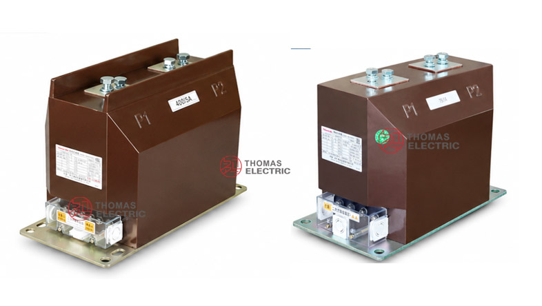
Product Display

Applications
- Indoor switchgear for 12 kV, 11 kV, 13.8 kV and 15 kV distribution networks
- Incoming and outgoing feeder cabinets requiring compact 180-platform CT installation
- Current measurement and electric energy metering circuits
- Relay protection circuits using 5P, 5P20, 10P, 10P15, 10P20 or project-specific protection classes
- Power monitoring, SCADA, automation and feeder supervision systems
- Projects requiring one mechanical platform with different secondary accuracy combinations
Features
- Same C2/180 platform: Both models share the 180 structural family, allowing users to compare different electrical configurations under a similar installation concept.
- System voltage coverage: Suitable for common 12 kV, 11 kV, 13.8 kV and 15 kV medium-voltage switchgear applications when insulation coordination is confirmed.
- Compact support structure: The 180 platform offers a practical balance between cabinet space, primary terminal clearance and secondary terminal access.
- C2 and C2Q options: C2/180 is suitable for standard metering/protection use, while C2Q/180/3 supports more detailed technical selection groups.
- Multiple accuracy combinations: Supports measurement classes such as 0.2 and 0.5, and protection classes such as 5P, 5P20, 10P, 10P15 and 10P20.
- High-current layout options: Drawings show separate primary terminal layouts for lower-current ranges and higher-current ranges such as 1000 A to 3150 A.
Principle
The LZZBJ9-10C2/180 platform converts primary current into a standardized secondary current by electromagnetic induction. Primary current flows through the primary conductor path, produces magnetic flux in the core and induces a proportional current in the secondary winding. The epoxy resin body separates the medium-voltage primary side from the low-voltage measurement and protection circuits.
For the C2/180 version, selection is usually based on rated ratio, burden and the required measuring/protection class. For the C2Q/180/3 version, the engineering focus is deeper: different technical table groups may correspond to different accuracy combinations, secondary outputs and protection-performance requirements. Each secondary circuit should be selected according to its actual function.
Model Designation

| Code | Meaning |
|---|---|
| L | Current transformer |
| Z | Indoor type / support structure |
| Z | Epoxy resin casting insulation |
| B | Protection level available |
| J | Strengthened design |
| 9 | Design serial number |
| 10 | 10 kV catalogue class; applicable to 12 kV, 11 kV, 13.8 kV and 15 kV system projects when insulation coordination is confirmed |
| C2 | Standard C2 structure platform |
| C2Q | Extended C2Q structure / technical selection variant |
| 180 | 180 nominal structure platform |
| 3 | Extended secondary technical table / configuration code |
Technical Data
| Item | Specification |
|---|---|
| System voltage application | 12 kV, 11 kV, 13.8 kV and 15 kV systems |
| Rated insulation level | 12/42/75 kV reference; final insulation by technical agreement |
| Rated frequency | 50 Hz; 60 Hz available by project confirmation |
| Rated secondary current | 5 A or 1 A |
| C2/180 rated primary current range | 5 A to 3150 A reference range according to supplied data |
| C2Q/180/3 rated primary current range | 10 A to 3150 A reference range according to supplied data |
| Measurement accuracy options | 0.2, 0.5 and project-specific measuring classes |
| Protection accuracy options | 5P, 5P20, 10P, 10P15, 10P20 and project-specific protection classes |
| Rated output | 10 VA to 150 VA depending on model, ratio, accuracy class and secondary configuration |
| Rated short-time thermal current | Up to 100 kA/1s reference according to ratio and configuration |
| Rated dynamic current | Up to 250 kA reference according to ratio and configuration |
| Surface creepage distance | 245 mm reference for C2Q/180/3 sample data |
| Approximate weight | 36 kg reference for C2Q/180/3; C2/180 weight by final drawing |
| Applicable standards | GB 20840.2-2014, IEC 61869-2:2012 and special project requirements |
C2/180 Configuration
The LZZBJ9-10C2/180 version is the standard configuration for the C2/180 platform. It is suitable for projects requiring conventional current measurement, metering and relay protection with a clear ratio range and straightforward secondary selection.
| Rated
Primary Current (A) |
Typical
Accuracy Combination |
Rated Output
Reference |
Short-Time
Thermal Current |
Rated
Dynamic Current |
|---|---|---|---|---|
| 5–30 | 0.2/0.5/5P20 0.5/0.5/5P20 |
10/20/15 20/20/15 |
0.5 kA to 4.5 kA | 1.25 kA to 11.25 kA |
| 40–100 | 0.2/0.5/5P20 0.5/5P20/5P20 |
10/20/15 20/20/15 |
6 kA to 21 kA | 15 kA to 52.5 kA |
| 150–500 | 0.2/0.5/5P20 0.5/5P20/5P20 |
10/20/15 20/20/15 |
31.5 kA to 63 kA | 80 kA to 157.5 kA |
| 600–1250 | 0.2/0.5/5P20 0.5/5P20/5P20 |
20/30/15 30/30/15 |
80 kA to 100 kA | 200 kA to 250 kA |
| 1500–3150 | 0.2/0.5/5P20 0.5/5P20/5P20 |
30/60/20 60/15/15 |
100 kA | 250 kA |
C2Q/180/3 Configuration
The LZZBJ9-10C2Q/180/3 version provides more detailed technical-table groups for users who need to compare secondary functions by accuracy class and output. It is suitable for projects where the CT specification must be matched carefully to metering, monitoring and protection requirements.
| Technical
Group |
Typical
Accuracy Combination |
Rated Output
Reference |
Engineering
Use |
|---|---|---|---|
| Group 1 | 0.1S / 0.5P 0.5 / 0.5 / 5P |
10 / 15 / 20 / 40 VA reference | Precision measurement and protection coordination where measuring accuracy is a priority. |
| Group 2 | 0.2 / 0.5 / 5P 0.5 / 0.5 / 5P |
10 / 15 / 20 / 30 VA reference | Balanced metering, monitoring and feeder protection applications. |
| Group 3 | 0.5 / 5P / 5P 0.5 / 5P / 8P |
15 / 20 / 25 / 30 VA reference | Protection-heavy applications where secondary functions are mainly used by relay or automation circuits. |
Note: The above tables are arranged from the supplied technical information for website selection reference. Final ratio, secondary current, rated output, accuracy class, short-time thermal current, dynamic current and terminal markings shall follow the nameplate, approved drawing and factory test report.
Terminals
Primary terminals are marked as P1 / P2. Secondary terminal markings depend on the selected configuration and secondary core quantity. Typical secondary terminals may include 1S1 / 1S2, 2S1 / 2S2 and additional terminals according to metering, protection or monitoring functions. Final wiring must follow the approved terminal diagram.
| Terminal Group | C2/180 | C2Q/180/3 | Engineering Note |
|---|---|---|---|
| Primary | P1 / P2 | P1 / P2 | Primary direction and busbar connection shall follow the outline drawing. |
| Measurement core | Specified by project | Specified by technical group | Used for panel indication, metering or monitoring signal input. |
| Protection core | 10P / 5P class options | 5P / 8P / project-specific options | Used for relay protection and automation circuits. |
| Shorting terminal | Recommended | Recommended | Required for safe CT secondary circuit maintenance. |
Busbar Layout
| Current Range | Primary Layout Reference |
Design Focus |
|---|---|---|
| I1n: 5 A–800 A | Lower-current terminal layout | Used for compact feeder and standard metering panels. |
| I1n: 1000 A–3150 A | High-current terminal layout | Requires confirmation of busbar spacing, bolt holes and cabinet clearance. |
| Project-specific high current | Customized terminal layout | Requires approved drawing before copper busbar processing. |
Service Conditions
- Installation location: indoor medium-voltage switchgear
- System voltage: 12 kV, 11 kV, 13.8 kV and 15 kV systems
- Rated frequency: 50 Hz; 60 Hz by project confirmation
- Rated secondary current: 5 A or 1 A
- Ambient temperature: -5°C to +40°C
- The installation environment should be free from severe vibration, conductive dust, corrosive gas, explosive medium, heavy pollution and abnormal condensation.
- For 13.8 kV and 15 kV systems, insulation coordination, creepage distance and project standard requirements must be confirmed before ordering.
Standards and Compliance
The LZZBJ9-10C2/180 and LZZBJ9-10C2Q/180/3 current transformers can be supplied according to GB 20840.2-2014, IEC 61869-2:2012 and special project requirements. For international product pages, this combined platform should be presented as an indoor epoxy cast-resin current transformer suitable for 12 kV, 11 kV, 13.8 kV and 15 kV system applications when insulation coordination is confirmed. Routine tests generally include ratio test, polarity verification, accuracy test, dielectric withstand test, insulation inspection and appearance inspection.
Installation and Dimensions

The 180 platform uses an indoor support-type structure with top primary terminals and lower secondary terminal arrangement. The supplied drawings show different primary terminal layouts for lower-current ranges and high-current ranges. For switchgear production, the final outline drawing must be confirmed before copper busbar processing, mounting-hole drilling and terminal wiring design.
Dimensions
| Item | Dimension / Note |
|---|---|
| Structure platform | C2/180 support-type platform |
| Configuration options | C2/180 standard type and C2Q/180/3 extended technical type |
| Primary terminal arrangement | Different layouts for lower-current and high-current versions |
| Surface creepage distance | 245 mm reference for C2Q/180/3 sample data |
| Approximate weight | 36 kg reference for C2Q/180/3 sample data |
| Drawing confirmation | Required before switchgear production, replacement or busbar fabrication |
Safety Notes
- Confirm whether the project requires C2/180 or C2Q/180/3 before ordering.
- Check system voltage, especially when the product is used for 13.8 kV or 15 kV systems.
- Confirm insulation level, creepage distance and applicable IEC / project standard before production.
- Use the correct primary terminal drawing for the selected current range.
- Confirm all secondary terminal markings before connecting meters, relays or monitoring devices.
- The secondary circuit of a current transformer must not be open-circuited when the primary circuit is energized.
- Before disconnecting instruments or relays, short-circuit the corresponding secondary circuit through a proper shorting block.
Ordering Info
- Product model: LZZBJ9-10C2/180 or LZZBJ9-10C2Q/180/3
- System voltage: 12 kV, 11 kV, 13.8 kV or 15 kV
- Rated primary current and rated secondary current
- Accuracy class combination and rated output for each secondary circuit
- Rated insulation level, creepage distance and applicable IEC / GB standard
- Required short-time thermal current and rated dynamic current
- Primary terminal drawing, busbar hole size and mounting dimension requirement
- Switchgear layout, cabinet clearance and primary terminal direction
- Quantity, certificates, routine test reports, labeling and packaging requirements
Selection Guide
- Confirm system voltage: Check whether the application is 12 kV, 11 kV, 13.8 kV or 15 kV, then confirm insulation coordination.
- Select platform version: Choose C2/180 for standard applications or C2Q/180/3 when deeper technical grouping is required.
- Define secondary functions: Assign each secondary circuit to metering, measurement, monitoring or protection.
- Select accuracy and output: Match accuracy class and VA output with connected meters, relays and cable burden.
- Verify fault withstand: Confirm short-time thermal current and dynamic current with the switchgear short-circuit level.
- Review busbar layout: Check primary terminal spacing, busbar width, bolt holes and cabinet clearance.
- Approve final drawing: Confirm outline dimensions, terminal diagram, nameplate data and routine test requirements before production.