Product Overview
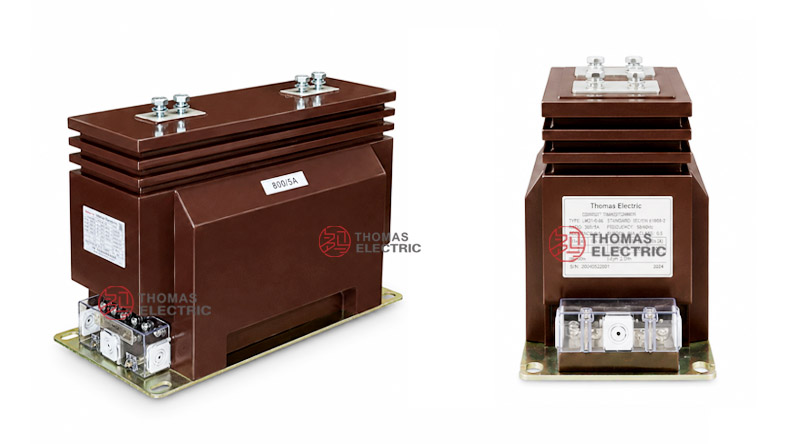
The LZZBJ9-10C3 / LZZBJ9-10C3Q3 / LZZBJ9-10C3Q4 current transformer is an indoor epoxy cast-resin, fully enclosed, post-type current transformer for medium-voltage AC power systems. It is designed for current measurement, energy metering, feeder monitoring and relay protection in 10kV, 11kV and 12kV class indoor switchgear.
This series uses a reinforced cast-resin insulated body with top primary terminals and a lower secondary terminal block. The C3 platform is suitable for higher-current feeder applications, while the Q3 and Q4 versions provide different outline and terminal layouts for switchgear integration. Final selection shall be confirmed according to rated current, short-circuit withstand level, terminal arrangement, cabinet space and approved drawing.
Product Type
| Item | Specification |
|---|---|
| Product name | Indoor Epoxy Cast-Resin Current Transformer |
| Model series | LZZBJ9-10C3 / LZZBJ9-10C3Q3 / LZZBJ9-10C3Q4 |
| Structure | Indoor, fully enclosed, post-type, epoxy cast-resin insulated structure |
| Voltage class | 10kV, 11kV and 12kV class medium-voltage systems |
| Rated insulation | 24/65/125kV reference; 12/42/75kV may apply to related 12kV-class configurations according to nameplate |
| Rated frequency | 50Hz / 60Hz |
| Secondary current | 5A or 1A |
| Installation | Indoor switchgear support-type installation |
| Applications | Current measurement, energy metering, relay protection, feeder monitoring and switchgear instrumentation |
Product Display


Applications
- 10kV, 11kV and 12kV class indoor medium-voltage distribution systems
- Metal-clad switchgear, incoming cabinets, outgoing feeder panels and metering cabinets
- Current measurement and electric energy metering circuits
- Relay protection circuits for feeders, transformers, motors and distribution lines
- SCADA, power monitoring and distribution automation systems
- High-current switchgear projects requiring 1000A to 3150A CT selections
Features
- Fully enclosed cast-resin body: The epoxy resin structure supports insulation strength, mechanical protection and stable indoor service performance.
- Post-type support design: The transformer integrates insulation support and current transformation functions for compact switchgear installation.
- High-current range: The series supports high-current feeder applications up to 3150A, with special higher-current layouts subject to drawing confirmation.
- Multi-core configuration: Metering and protection cores can be configured with accuracy combinations such as 0.2S/5P20/5P20, 0.5/0.5/5P20 and 5P20/5P20/5P20.
- 1A or 5A secondary output: Secondary current can be selected according to relay input, meter input, wiring distance and secondary burden.
- Q3 / Q4 structures: Different outlines support different terminal spacing, busbar layouts and switchgear installation requirements.
Principle
The LZZBJ9-10C3 current transformer operates according to electromagnetic induction. The primary current generates magnetic flux in the core, and the secondary winding outputs a proportional current signal to meters, relays or monitoring devices. The epoxy resin insulation separates the medium-voltage primary circuit from the secondary circuits.
For metering use, the secondary core must maintain the specified ratio accuracy and phase displacement within the rated burden. For protection use, the protection core must provide a reliable current signal during fault-current conditions and coordinate with relay settings. Rated short-time thermal current and rated dynamic current shall match the switchgear fault level.
Model Designation
| Code | Meaning |
|---|---|
| L | Current transformer |
| Z | Indoor type / post-type structure |
| Z | Epoxy resin cast insulation / fully enclosed structure |
| B | Protection class available |
| J | Reinforced / enhanced design |
| 9 | Design sequence code |
| 10 | 10kV catalogue voltage class; commonly used for 10kV, 11kV and 12kV class systems |
| C3 | Structure code for this product platform |
| Q3 / Q4 | Outline and installation variants for different switchgear layouts |
Technical Data
| Item | Specification |
|---|---|
| Rated voltage class | 10kV, 11kV and 12kV class indoor systems |
| Rated insulation level | 24/65/125kV reference according to sample data; final level by nameplate |
| Rated frequency | 50Hz / 60Hz |
| Rated primary current | 5A to 3150A reference range; special high-current configuration by agreement |
| Rated secondary current | 5A or 1A |
| Accuracy combination | 0.2S/5P20/5P20, 0.5/0.5/5P20, 0.5/5P20/5P20, 5P20/5P20/5P20 or project-specific combinations |
| Rated output | 20/20/20, 30/20/20, 20/30/20, 20/30/30, 30/30/30 or project-specific VA configuration |
| Altitude | ≤1500m standard installation reference |
| Ambient temperature | -5°C to +40°C |
| Applicable standards | GB/T 20840.1, GB/T 20840.2, IEC 61869-2:2012 and special project requirements |
Terminals
The product may be supplied with multiple secondary cores for metering and protection. Typical terminal markings include P1 / P2 for the primary side and 1S1 / 1S2, 2S1 / 2S2, 3S1 / 3S2 for secondary cores. Final terminal quantity and arrangement shall be confirmed according to the core configuration and approved drawing.
| Terminal Marking |
Function | Application Note |
|---|---|---|
| P1 / P2 | Primary terminals | Primary current direction and busbar connection shall follow the drawing and wiring diagram. |
| 1S1 / 1S2 | First secondary core | Usually used for metering or the first specified measurement core. |
| 2S1 / 2S2 | Second secondary core | Usually used for protection or additional measurement. |
| 3S1 / 3S2 | Third secondary core | Used when multiple protection or metering/protection combinations are specified. |
Selection Table
The following table summarizes common ratio ranges, accuracy combinations and short-circuit withstand values. Long headers and shared values are wrapped to keep the table suitable for responsive website layouts.
| Rated Primary Current (A) |
Accuracy Class Combination |
Rated Output (VA) |
Rated Short-Time Thermal Current |
Rated Dynamic Current (kA) |
|---|---|---|---|---|
| 5–300 | 0.2S / 5P20 / 5P20 0.5 / 0.5 / 5P20 0.5 / 5P20 / 5P20 5P20 / 5P20 / 5P20 |
20 / 20 / 20 30 / 20 / 20 20 / 30 / 20 20 / 30 / 30 30 / 30 / 30 |
150 × I1n | 375 × I1n |
| 400–800 | 63kA | 130 | ||
| 1000–1250 | 80kA | 160 | ||
| 1500–3150 | 100kA | 160 |
Note: If user requirements exceed the listed data, final parameters may be agreed between manufacturer and purchaser. Nameplate data, approved drawings and factory test reports shall prevail.
High-Current Reference
| Current Range | Terminal / Mounting Reference |
Application Note |
|---|---|---|
| I1n: 5A–1000A | Standard primary terminal arrangement | Suitable for common feeder and measurement circuits. |
| I1n: 1200A–3150A | Large-current terminal arrangement | Used for higher-current switchgear and main feeder applications. |
| I1n: 3200A–4000A | Special high-current arrangement | Requires drawing confirmation and technical agreement before production. |
Service Conditions
- Installation location: indoor medium-voltage switchgear
- System voltage: 10kV, 11kV and 12kV class networks
- Rated frequency: 50Hz / 60Hz
- Ambient temperature: -5°C to +40°C
- Altitude: ≤1500m standard reference
- The installation environment should be free from severe vibration, conductive dust, corrosive gas, explosive medium, heavy pollution and abnormal condensation.
- For high altitude, humid, coastal, high-pollution or special switchgear conditions, technical confirmation is required before ordering.
Standards and Compliance
The LZZBJ9-10C3 current transformer conforms to GB/T 20840.1, GB/T 20840.2, IEC 61869-2:2012 and special project requirements. Routine tests typically include ratio test, polarity verification, accuracy test, dielectric withstand test, insulation inspection and appearance inspection. Additional type test documents or special test requirements can be confirmed according to project specifications.
Installation and Dimensions

The product adopts an indoor post-type structure with top primary terminals and lower secondary terminal arrangement. The overall dimensions and primary terminal configuration differ according to current range. Cabinet design shall be based on the approved drawing, especially for 1200A and above applications.
Dimensions
| Item | Dimension / Note |
|---|---|
| Overall length | 460mm reference |
| Overall width | 200mm reference |
| Overall height | 320 ± 10mm reference |
| Mounting length | 425mm / 390mm reference according to terminal arrangement |
| Primary terminal range | Different layouts for 5A–1000A, 1200A–3150A and 3200A–4000A |
| Drawing confirmation | Required before switchgear production or replacement |
Safety Notes
- Confirm model, current ratio, secondary current, accuracy combination, rated output and insulation level before installation.
- Check mounting space, busbar connection, primary terminal position, secondary terminal layout and phase clearance before assembly.
- Use the correct drawing for the selected current range, especially for 1200A and above terminal arrangements.
- Connect P1/P2 and secondary terminals according to polarity markings and the project wiring diagram.
- The secondary circuit of a current transformer must not be open-circuited when the primary circuit is energized.
- Before disconnecting meters or relays, short-circuit the secondary circuit through an approved shorting terminal block.
- Installation and maintenance shall be performed by qualified medium-voltage electrical personnel.
Ordering Info
- Product model: LZZBJ9-10C3, LZZBJ9-10C3Q3 or LZZBJ9-10C3Q4
- Rated primary current and rated secondary current
- Accuracy class combination and rated output for each core
- Rated insulation level and applicable standard
- Required short-time thermal current and dynamic current
- Secondary terminal quantity and terminal marking requirement
- Switchgear layout, mounting dimensions and primary terminal direction
- Quantity, certificates, routine test reports, labeling and packaging requirements
Selection Guide
- Confirm voltage class: Use this CT for indoor 10kV, 11kV and 12kV class systems.
- Confirm model variant: Select C3, C3Q3 or C3Q4 according to switchgear layout, installation dimensions and current range.
- Select current ratio: Choose rated primary current according to feeder load, metering range and protection settings.
- Define core functions: Specify metering and protection cores separately, including accuracy class and rated output.
- Check rated burden: Confirm that meter, relay and cable burden do not exceed the rated output of each secondary core.
- Verify fault rating: Rated short-time thermal current and rated dynamic current shall match the switchgear fault level.
- Confirm dimensions: Check mounting holes, primary terminal layout, secondary terminals and cabinet clearance before production.