Product Overview
The LZZBJ9-12/190b/4S current transformer, also referenced as AS12/190b/4S or AS12190b/4S, is an indoor epoxy cast-resin, dry-type, fully enclosed support-structure current transformer for medium-voltage AC power systems. It is designed for current measurement, electric energy metering, feeder monitoring and relay protection in 10kV, 11kV and 12kV class switchgear systems.
The product encloses the primary winding, secondary winding and annular magnetic core inside an epoxy resin casting body. This dry-type insulation structure provides mechanical strength, moisture resistance and stable insulation performance for indoor medium-voltage operation. The product is suitable for switchgear applications with rated frequency of 50Hz or 60Hz and highest voltage for equipment up to 12kV.
The 190b / 4S structure indicates a specific nominal width and secondary schematic arrangement. It is suitable for projects requiring multiple secondary cores, such as combined metering and relay protection circuits. Final selection shall be confirmed according to current ratio, secondary output, accuracy-class combination, rated burden, short-circuit withstand requirement and approved outline drawing.
Product Type
| Item | Specification |
|---|---|
| Product name | Indoor Epoxy Cast-Resin Current Transformer |
| Model series | LZZBJ9-12/190b/4S / AS12/190b/4S / AS12190b/4S |
| Structure | Indoor, dry-type, fully enclosed, support-type epoxy cast-resin structure |
| Voltage class | 10kV, 11kV and 12kV class medium-voltage systems |
| Highest voltage for equipment | 7.2kV / 12kV according to project configuration |
| Rated insulation | 12/42/75kV reference; final value by nameplate and technical agreement |
| Rated frequency | 50Hz / 60Hz |
| Secondary current | 5A or 1A |
| Phase | Single phase |
| Installation | Indoor busbar / support-type switchgear installation |
| Applications | Protection, measurement, energy metering and feeder monitoring |
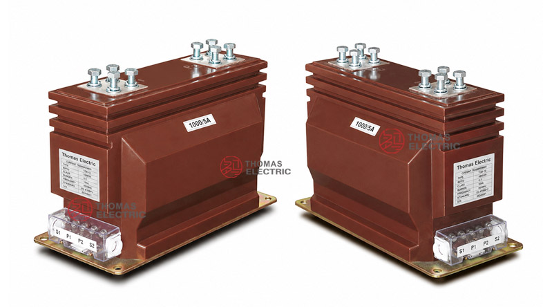
Product Display


Applications
- 10kV, 11kV and 12kV class indoor medium-voltage switchgear
- Metal-clad switchgear, feeder panels, incoming cabinets and outgoing cabinets
- Current measurement and electric energy metering circuits
- Relay protection circuits for feeders, transformers, motors and distribution lines
- SCADA, power monitoring and distribution automation systems
- Projects requiring multi-core CT configurations for metering and protection
Features
- Fully enclosed dry-type insulation: The primary winding, secondary winding and annular core are cast together in the epoxy resin body for stable indoor insulation.
- Support construction: The product provides both current transformation and insulation support functions inside medium-voltage switchgear.
- Multi-core 4S configuration: The 4S schematic arrangement supports multiple secondary circuits for metering, measurement and relay protection.
- Omni-directional installation: The cast-resin structure supports flexible switchgear installation when the mounting layout and terminal direction are confirmed by drawing.
- Moisture and pollution resistance: The epoxy resin body is suitable for indoor applications where humidity, dust and operating environment must be considered.
- 1A or 5A secondary output: The secondary current can be selected according to meter input, relay input, secondary wiring distance and burden requirement.
Principle
The LZZBJ9-12/190b/4S current transformer operates according to electromagnetic induction. The primary current produces magnetic flux in the annular core, and the secondary winding outputs a proportional current signal to meters, relays or monitoring devices. The epoxy resin casting body provides electrical insulation between the medium-voltage primary circuit and the low-voltage secondary circuits.
For metering applications, the secondary core shall maintain ratio accuracy and phase displacement under the rated burden. For protection applications, the protection core shall provide a reliable current signal under fault-current conditions and coordinate with relay settings. The rated short-time thermal current and rated dynamic current must match the switchgear fault-current level.
Model Designation
The model code can be interpreted as follows:
| Code | Meaning |
|---|---|
| L | Current transformer |
| Z | Pillar / post type structure |
| Z | Epoxy pouring / cast-resin insulation |
| B | With protection level |
| J | Strengthened design |
| 9 | Design serial number |
| 12 | Maximum operating voltage / 12kV class; also used in the AS12 alternative model designation |
| 190b | Nominal width / structure dimension code |
| 4S | Secondary schematic code / multi-secondary configuration |
| AS12 | Alternative series designation for the same 12kV indoor epoxy cast-resin CT platform |
Technical Data
| Item | Specification |
|---|---|
| Rated voltage class | 10kV, 11kV and 12kV class indoor systems |
| Highest voltage for equipment | 7.2kV / 12kV according to project configuration |
| Rated insulation level | 12/42/75kV reference; final value according to nameplate |
| Rated frequency | 50Hz / 60Hz |
| Rated primary current | 10A to 3150A reference range; 1000A–3150A high-current configurations available according to drawing |
| Rated secondary current | 5A or 1A |
| Accuracy combination | 0.2S/0.5/5P10, 0.2S/0.5/5P20, 0.2S/0.5/5P30, 0.5/5P10, 0.5/5P20, 0.5/5P30 or project-specific combinations |
| Rated output | 15/20/50/50, 15/20/30/30, 15/20/25/25, 15/20/15/15, 20/30/60/60, 20/30/40/40, 20/30/30/30 or 20/30/20/20 VA according to configuration |
| Ambient temperature | -25°C to +40°C |
| Insulating medium | Epoxy resin |
| Installation type | Indoor support-type / busbar-type installation |
| Applicable standards | GB 20840.1-2010, GB 20840.2-2014 and special project requirements |
Terminals
The 4S schematic structure indicates a multi-secondary arrangement. The product may be supplied with several secondary cores for measurement and protection. Typical terminal markings include P1 / P2 for the primary side and 1S1 / 1S2, 2S1 / 2S2, 3S1 / 3S2 and optional additional secondary terminals according to the approved drawing.
| Terminal
Marking |
Function | Application Note |
|---|---|---|
| P1 / P2 | Primary terminals | Primary current direction and busbar connection shall follow the project wiring diagram. |
| 1S1 / 1S2 | First secondary core | Usually used for metering or the first measurement circuit. |
| 2S1 / 2S2 | Second secondary core | Used for measurement or protection according to the selected accuracy combination. |
| 3S1 / 3S2 | Third secondary core | Used for protection or additional relay circuit when required. |
| 4S circuit | Fourth secondary schematic | Terminal arrangement and core function must be confirmed by nameplate and drawing. |
Selection Table
The following selection table is arranged by current range. Long accuracy and output data are wrapped into multiple lines to improve readability on website pages and mobile layouts.
| Rated
Primary Current (A) |
Accuracy
Class Combination |
Rated
Output |
Short-Time
Thermal Current |
Rated
Dynamic Current (kA) |
|---|---|---|---|---|
| 10–40 | 0.2S / 0.5 / 5P10 0.2S / 0.5 / 5P15 0.2S / 0.5 / 5P20 0.2S / 0.5 / 5P30 |
15 / 20 / 50 / 50 15 / 20 / 30 / 30 15 / 20 / 25 / 25 15 / 20 / 15 / 15 |
150 × I1n | 375 × I1n |
| 50–100 | 200 × I1n | 500 × I1n | ||
| 150–250 | 32kA | 80 | ||
| 300–400 | 50kA | 125 | ||
| 500–600 | 63kA | 160 | ||
| 750–800 | 20 / 30 / 60 / 60 20 / 30 / 40 / 40 20 / 30 / 30 / 30 20 / 30 / 20 / 20 |
80kA | 200 | |
| 1000–3150 | 100kA | 250 | ||
| Special ratio | By technical agreement | By agreement |
Note: The above values are for technical selection reference. If project requirements exceed the listed range, final parameters shall be confirmed by agreement between manufacturer and purchaser. Nameplate data, approved drawings and factory test reports shall prevail.
High-Current Reference
| Current
Range |
Terminal / Mounting
Reference |
Application
Note |
|---|---|---|
| 800A ≤ I1n | Standard large-current terminal layout | Used for medium and high-current feeder applications. |
| 1000A ≤ I1n ≤ 3150A | Enhanced primary terminal layout | Requires confirmation of busbar size, terminal spacing and switchgear clearance. |
| Special high-current projects | Project-specific terminal and mounting arrangement | Requires approved outline drawing before production. |
Service Conditions
- Installation location: indoor medium-voltage switchgear
- System voltage: 10kV, 11kV and 12kV class networks
- Rated frequency: 50Hz / 60Hz
- Ambient temperature: -25°C to +40°C
- The installation environment should be free from severe vibration, conductive dust, corrosive gas, explosive medium, heavy pollution and abnormal condensation.
- For high altitude, humid, coastal, high-pollution or special switchgear conditions, technical confirmation is required before ordering.
Standards and Compliance
The LZZBJ9-12/190b/4S current transformer can be supplied according to GB 20840.1-2010, GB 20840.2-2014 and special project requirements. For international projects, IEC 61869-1 and IEC 61869-2 may be used as reference standards when required by the technical agreement. Routine tests typically include ratio test, polarity verification, accuracy test, dielectric withstand test, insulation inspection and appearance inspection.
Installation and Dimensions

The product adopts an indoor support-type structure with top primary terminals and lower secondary terminal arrangement. The overall dimensions and primary terminal layout shall be confirmed according to the rated current range. Special attention is required for high-current versions above 1000A because busbar connection, terminal spacing and cabinet clearance may change according to the selected drawing.
Dimensions
| Item | Dimension / Note |
|---|---|
| Overall length | 400mm reference according to sample drawing |
| Overall height | 261mm reference |
| Base length | 340mm / 380 ± 5mm reference according to drawing |
| Overall width | 190mm reference |
| Terminal arrangement | Different layouts for 800A ≤ I1n and 1000A ≤ I1n ≤ 3150A |
| Mounting holes | 4-M10 or 8-M10 reference according to primary terminal arrangement |
| Drawing confirmation | Required before switchgear production or replacement |
Safety Notes
- Confirm model, current ratio, secondary current, accuracy combination, rated output and insulation level before installation.
- Check mounting space, busbar connection, primary terminal position, secondary terminal layout and phase clearance before assembly.
- Use the correct drawing for the selected current range and terminal arrangement.
- Connect P1/P2 and secondary terminals according to polarity markings and the project wiring diagram.
- The secondary circuit of a current transformer must not be open-circuited when the primary circuit is energized.
- Before disconnecting meters or relays, short-circuit the secondary circuit through an approved shorting terminal block.
- Installation and maintenance shall be performed by qualified medium-voltage electrical personnel.
Ordering Info
- Product model: LZZBJ9-12/190b/4S, AS12/190b/4S or AS12190b/4S
- Rated primary current and rated secondary current
- Accuracy class combination and rated output for each core
- Rated insulation level and applicable standard
- Required short-time thermal current and dynamic current
- Secondary core quantity, schematic code and terminal marking requirement
- Switchgear layout, mounting dimensions and primary terminal direction
- Quantity, certificates, routine test reports, labeling and packaging requirements
Selection Guide
- Confirm voltage class: Select this CT for 10kV, 11kV and 12kV class indoor switchgear.
- Confirm model structure: Use LZZBJ9-12/190b/4S when the switchgear requires the 190b nominal width and 4S secondary schematic layout.
- Select current ratio: Choose the rated primary current according to feeder load, metering range and protection setting.
- Define core functions: Specify each secondary core separately, including accuracy class, protection level and rated output.
- Check rated burden: Confirm that meter, relay and cable burden do not exceed the rated output of each secondary core.
- Verify fault rating: Rated short-time thermal current and rated dynamic current shall match the switchgear fault level.
- Confirm dimensions: Check primary terminal layout, busbar spacing, secondary terminals and cabinet clearance before production.