Product Overview
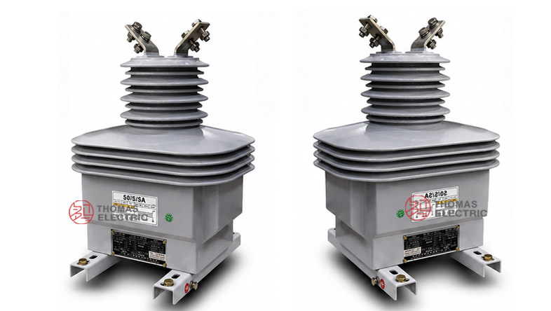
The LZZBW1-35 / LZZBW2-35Q outdoor epoxy resin cast current transformer is a dry-type medium-voltage / high-voltage instrument transformer designed for 33kV, 35kV and 40.5kV outdoor distribution systems. It is used for current measurement, energy metering and relay protection in AC power networks with rated frequency of 50Hz or 60Hz. The product adopts an outdoor epoxy cast-resin fully enclosed structure, providing stable insulation performance, mechanical strength and weather resistance for exposed installation environments.
This series should be positioned as a 40.5kV-class outdoor dry-type current transformer for distribution feeders, outdoor switchyards, compact substations and utility metering points. Compared with oil-immersed outdoor CTs, it is oil-free and easier to maintain. Compared with 24kV outdoor epoxy CTs, the LZZBW1-35 / LZZBW2-35Q platform is designed for higher insulation coordination, with a typical rated insulation level of 40.5/95/185kV for 33kV / 35kV / 40.5kV systems.
Product Type


| Item | Specification |
|---|---|
| Product name | Outdoor Epoxy Resin Cast Current Transformer |
| Model series | LZZBW1-35 / LZZBW2-35Q |
| Installation condition | Outdoor |
| Structure | Pillar-type, fully enclosed epoxy cast-resin structure |
| Application | Current measurement, energy metering and relay protection |
| Voltage class | 33kV / 35kV / 40.5kV class systems |
| Rated insulation level | 40.5/95/185kV |
| Rated frequency | 50Hz or 60Hz |
| Rated secondary current | 5A or 1A |
| Typical construction | Outdoor dry-type epoxy insulation with top primary terminals and front secondary terminal box |
Model Explanation
- L: Current transformer.
- Z: Pillar-type / post-type current transformer structure.
- Z: Epoxy resin cast insulation.
- B: Current transformer series with metering and protection winding options.
- W: Outdoor type.
- 1 / 2: Design sequence or structural platform code.
- 35: 35kV class product platform, suitable for 33kV / 35kV / 40.5kV systems.
- Q: Enhanced outdoor structure / project-specific structural variant.
- 5A or 1A: Rated secondary current option.
- Accuracy combination: Metering and protection combinations such as 0.2S/0.5, 0.2S/10P10, 0.5/10P10, 10P10/10P10 and 10P15/10P15 according to project requirements.
Applications
- 33kV, 35kV and 40.5kV outdoor medium-voltage distribution systems
- Outdoor substations, utility metering points and feeder protection circuits
- Pole-mounted or platform-mounted outdoor metering equipment
- Distribution transformer incoming / outgoing feeder measurement
- Industrial 35kV outdoor power distribution and plant substations
- Renewable energy grid connection systems, including solar and wind farm collection lines
- Projects requiring oil-free outdoor instrument transformers for high-humidity or maintenance-sensitive sites
Features
- 40.5/95/185kV insulation level: Suitable for 33kV / 35kV / 40.5kV outdoor insulation coordination.
- Outdoor dry-type epoxy body: Fully enclosed epoxy cast-resin insulation supports outdoor service and eliminates transformer oil.
- Flexible secondary output: 5A or 1A secondary current can be selected according to meters, relays and secondary cable length.
- Metering and protection combinations: Supports metering classes such as 0.2S, 0.2 and 0.5, as well as protection classes such as 10P10 and 10P15.
- Outdoor terminal access: Top primary terminal arrangement and front secondary terminal box simplify installation and maintenance inspection.
- Multiple structural variants: LZZBW1-35 and LZZBW2-35Q can be selected according to mounting layout, conductor connection and project design.
Operating Conditions
- Outdoor installation
- Ambient temperature: -5°C to +40°C
- Rated frequency: 50Hz / 60Hz
- Altitude: ≤ 1000m
- No severe pollution, corrosive gas, or explosive atmosphere
- Suitable for outdoor humidity, UV exposure, and tracking-resistant insulation applications
Operating Principle
The LZZBW1-35 / LZZBW2-35Q current transformer converts the primary current of a 33kV / 35kV / 40.5kV circuit into a standardized secondary current signal. The secondary output is connected to meters, relays or monitoring equipment, allowing safe measurement and protection without direct connection to the high-voltage primary circuit.
For metering circuits, the selected metering core must maintain the required ratio accuracy and phase displacement within the rated burden. For protection circuits, the protection core must provide dependable secondary output during fault-current conditions. Therefore, current ratio, secondary current, accuracy class, rated output, short-time thermal current and dynamic current should be confirmed together during technical selection.
Technical Data
| Parameter | Specification |
|---|---|
| Model | LZZBW1-35 / LZZBW2-35Q |
| Product type | Outdoor epoxy resin cast current transformer |
| System voltage class | 33kV / 35kV / 40.5kV |
| Rated insulation level | 40.5/95/185kV |
| Rated frequency | 50Hz or 60Hz |
| Rated secondary current | 5A or 1A |
| Rated primary current | 15A to 2000A reference range according to catalogue data and project selection |
| Accuracy class combination | 0.2S/0.5, 0.2S/10P10, 0.5/10P10, 10P10/10P10, 10P15/10P15 and related project combinations |
| Rated output | 10VA, 15VA, 20VA, 30VA or higher combinations depending on ratio and winding function |
| Ambient temperature | -5°C to +40°C reference; special outdoor service conditions by agreement |
| Installation | Outdoor |
| Applicable standards | IEC 61869-1, IEC 61869-2, GB/T 20840.1, GB/T 20840.2; project-specific requirements by agreement |
Selection Table
The following selection table is reorganized from the supplied catalogue information and optimized for website display. Long headings and accuracy-class cells are split into multiple lines to avoid table overflow.
| Rated Primary Current (A) |
Accuracy Class Combination |
Rated Output (VA) |
Rated Short-Time Thermal Current |
Rated Dynamic Current |
|---|---|---|---|---|
| 15 | 0.2S / 0.5 0.2S / 10P10 0.5 / 10P10 10P10 / 10P10 10P15 / 10P15 |
10 / 10 15 / 15 |
6kA | 15kA |
| 20 | 10 / 10 15 / 15 |
8kA | 20kA | |
| 30 | 10 / 10 15 / 15 |
10kA | 25kA | |
| 40 | 10 / 10 15 / 15 |
15kA | 37.5kA | |
| 50 | 10 / 10 15 / 15 |
20kA | 50kA | |
| 75 | 10 / 10 15 / 15 |
25kA | 62.5kA | |
| 100 | 15 / 15 20 / 20 |
31.5kA | 78.75kA | |
| 150–300 | 15 / 15 20 / 20 |
45kA | 112.5kA | |
| 400–600 | 0.2S / 10P10 0.5 / 10P10 10P10 / 10P10 10P15 / 10P15 |
20 / 20 30 / 30 |
63kA | 157.5kA |
| 800–1000 | 30 / 30 30 / 30 / 30 |
80kA | 200kA | |
| 1200–2000 | 30 / 30 30 / 30 / 30 |
100kA | 250kA |
Note: The table is for preliminary selection. Final ratio, rated burden, accuracy class, protection class, short-time thermal current, dynamic current and terminal arrangement shall be confirmed according to the nameplate, approved drawing and factory test report.
Installation and Dimensions

The LZZBW1-35 / LZZBW2-35Q is installed outdoors on a stable mounting plate, steel bracket, pole-mounted structure or substation foundation. The product drawings show different outline dimensions according to current range, including structures for 15–400A, 500–1000A and 1200–2000A. Before installation, the mounting hole layout, conductor direction, primary terminal arrangement, grounding position and secondary terminal box access should be confirmed with the approved drawing.
Windings & Terminal Marking
The primary terminals are normally marked P1 and P2. The secondary terminals are arranged in the front terminal box and should be connected according to the approved wiring diagram. For multi-core metering and protection configurations, each secondary winding should be assigned clearly before production.
| Terminal | Function | Application Note |
|---|---|---|
| P1 / P2 | Primary terminals | Used for primary current direction and polarity reference. |
| S1 / S2 | Single secondary winding | Used when one secondary output is specified. |
| 1S1 / 1S2 | First secondary winding | Usually assigned to metering or current measurement. |
| 2S1 / 2S2 | Second secondary winding | Usually assigned to relay protection. |
| 3S1 / 3S2 | Additional secondary winding when specified | Used for backup protection, independent monitoring or additional relay circuit. |
| Grounding point | Secondary / base grounding reference | One point of the secondary circuit and the CT base should be grounded according to project practice. |
Standards and Compliance
For international documentation, the LZZBW1-35 / LZZBW2-35Q series should be specified according to IEC 61869-1 and IEC 61869-2. For GB-based documentation, GB/T 20840.1 and GB/T 20840.2 can be used. The supplied catalogue information references GB20840.2-2014 and IEC 61869-2:2012. Final compliance scope should be confirmed according to the project technical agreement and routine test plan.
Safety Notes
- Confirm voltage class, rated insulation level, current ratio, secondary current, accuracy class and rated output before installation.
- Check the approved drawing for the correct current-range structure before fixing the CT to the outdoor support.
- Verify P1 / P2 polarity and secondary terminal marking before wiring meters, relays or test devices.
- Confirm primary conductor clearance, bracket strength, grounding point and terminal box access.
- Ground the CT base and one point of the secondary circuit according to the station grounding design.
- The CT secondary circuit must not be open-circuited while primary current is flowing.
- Before disconnecting meters, relays or test equipment, short-circuit the secondary circuit with an approved shorting device.
- Seal the secondary terminal box after wiring to reduce moisture ingress and maintain outdoor reliability.
- Installation and commissioning shall be performed by qualified medium-voltage electrical personnel.
Selection Guide
- Confirm voltage level: Use this series for 33kV, 35kV and 40.5kV outdoor distribution systems.
- Confirm outdoor dry-type requirement: Select this product when oil-free epoxy resin insulation is preferred over oil-immersed CTs.
- Select current ratio: Choose the primary current according to feeder load, metering range and protection setting.
- Choose secondary current: Use 5A for conventional meters and relays; use 1A for long secondary wiring or lower cable burden.
- Define accuracy class: Use 0.2S / 0.2 / 0.5 for measurement or metering, and 10P10 / 10P15 for protection.
- Check short-circuit withstand: Confirm Ith and Idyn against the system fault level at the installation point.
- Approve installation drawing: Select the correct mechanical drawing according to the current range and confirm all terminal and mounting details before production.