Product Overview
The LZZW6-15A(B) pole-mounted current transformer is a fully enclosed outdoor current transformer for medium-voltage distribution systems. It is designed for current measurement, electric energy metering and relay protection in 15 kV class outdoor power networks, including common 13.8 kV and 15 kV system applications.
This product should be positioned as a pole-mounted outdoor CT for higher insulation-class distribution networks, not as a conventional indoor switchgear CT. Compared with indoor epoxy cast-resin CTs, the LZZW6-15A(B) focuses on outdoor insulation reliability, rain and humidity resistance, creepage distance, terminal sealing, primary pole-mounted connection, and long-term operation in exposed distribution environments. The A/B structure also allows the same product family to cover different primary-current ranges and connection arrangements.
Product Type
| Item | Specification |
|---|---|
| Product name | 15kV Pole-Mounted Fully Enclosed Outdoor Current Transformer |
| Model series | LZZW6-15A(B) |
| Installation condition | Outdoor / pole-mounted |
| Structure | Fully enclosed outdoor cast-resin insulation structure |
| System voltage application | 13.8 kV and 15 kV class medium-voltage systems |
| Rated insulation level | 17.5/55/105 kV |
| Rated frequency | 50 Hz / 60 Hz |
| Rated secondary current | 5 A or 1 A |
| Ambient temperature | -25°C to +55°C |
| Typical application | Outdoor metering, current measurement, relay protection and distribution-line monitoring |
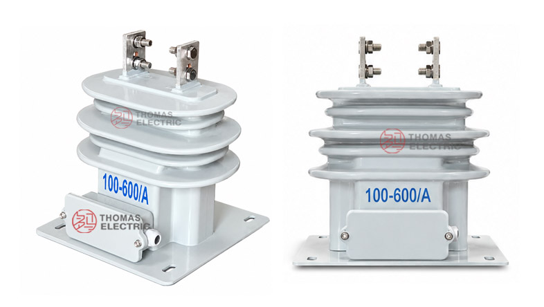
Product Display
 Pole-Mounted Fully Enclosed Outdoor Current Transformer Thomas Electric")
 Pole-Mounted Fully Enclosed Outdoor Current Transformer Thomas Electric")
Applications
- 15 kV class outdoor distribution feeders
- 13.8 kV utility and industrial power distribution systems
- Pole-mounted metering and protection installations
- Outdoor high-voltage metering units and metering boxes
- Distribution automation, feeder monitoring and current signal collection
- Outdoor installations requiring rain-resistant, humidity-resistant and fully enclosed insulation design
Features
- 15kV outdoor positioning: Designed for higher insulation-class outdoor distribution systems, especially 13.8 kV and 15 kV networks.
- Pole-mounted construction: Suitable for outdoor pole installation where mechanical stability, terminal sealing and wiring protection are critical.
- Fully enclosed insulation body: The resin-cast structure protects the primary conductor, secondary winding and magnetic core from outdoor humidity and contamination.
- A/B structural family: The 15A and 15B versions support different primary-current ranges and terminal arrangements within one outdoor CT platform.
- Metering and protection use: Supports current measurement, energy metering and relay protection with selectable 5 A or 1 A secondary current.
- Outdoor wiring diagram support: Supplied wiring diagrams help distinguish primary and secondary terminal connections for measurement and protection circuits.
Principle
The LZZW6-15A(B) current transformer converts medium-voltage primary current into a standard secondary current through electromagnetic induction. The primary side is connected to the outdoor line or pole-mounted equipment, while the secondary side supplies a 5 A or 1 A signal to meters, relays or monitoring devices.
For this outdoor pole-mounted CT, engineering selection must consider more than current ratio and accuracy. The rated insulation level, creepage distance, outdoor pollution condition, secondary terminal sealing, wiring diagram, mounting base, rain exposure and mechanical stability should be confirmed together. This positioning helps separate the LZZW6-15A(B) page from indoor switchgear CT pages and from lower-voltage outdoor CT pages.
Model Designation
 Pole-Mounted Fully Enclosed Outdoor Current Transformer Thomas Electric")
Technical Data
| Item | Specification |
|---|---|
| Model | LZZW6-15A(B) |
| Installation condition | Outdoor / pole-mounted |
| Rated voltage class | 15 kV class; suitable for 13.8 kV and 15 kV systems when project insulation coordination is confirmed |
| Rated insulation level | 17.5/55/105 kV |
| Rated frequency | 50 Hz / 60 Hz |
| Rated secondary current | 5 A or 1 A |
| Ambient temperature | -25°C to +55°C |
| Accuracy class options | 0.2S, 0.2, 0.5S, 0.5 and project-specific metering/protection combinations |
| Rated output | Typical 15 VA to 50 VA range according to current ratio and accuracy class |
| Applicable standards | GB 20840.1-2010, GB 20840.2-2014 and special project requirements |
15A Configuration
The LZZW6-15A configuration is suitable for lower and medium primary-current outdoor metering or protection applications. The technical table shows 15A data with selectable measuring accuracy levels and short-time thermal current values arranged by primary current range.
| Rated
Primary Current (A) |
Accuracy
Class Options |
Rated
Output(VA) |
Short-Time
Thermal Current |
Rated
Dynamic Current |
|---|---|---|---|---|
| 5–300 | 0.2S / 0.2 / 0.5S / 0.5 | 20 / 30 / 30 / 40 | 8–50 × I1n / 2s reference | 20–100 × I1n reference |
| 400 | 0.2S / 0.2 / 0.5S / 0.5 | 30 / 30 / 40 / 40 | 31.5 kA | 80 kA |
| 500 | 0.2S / 0.2 / 0.5S / 0.5 | 40 / 40 / 40 / 50 | 45 kA | 112.5 kA |
| 600 | 0.2S / 0.2 / 0.5S / 0.5 | 50 / 50 / 60 / 50 | 63 kA | 130 kA |
15B Configuration
The LZZW6-15B configuration is arranged for compound or higher-current applications. The supplied dimensional drawing shows a dedicated 15B layout and a separate terminal reference for current ratios such as 150/5 A and 300/5 A.
| Rated
Primary Current (A) |
Accuracy
Class Options |
Rated
Output(VA) |
Short-Time
Thermal Current |
Rated
Dynamic Current |
|---|---|---|---|---|
| 50–200 / 100–200 150–300 / 300–400 |
0.2S / 0.2 / 0.5S / 0.5 | 20 / 25 / 30 / 30 reference | 25–50 × I1n / 2s reference | 62.5–125 × I1n reference |
Note: The above values are organized from the supplied technical sheet for website selection reference. Final current ratio, secondary current, rated output, accuracy class, thermal current, dynamic current, terminal marking and wiring diagram shall follow the approved drawing, nameplate and factory test report.
Outdoor Installation
| Outdoor Factor | Engineering Focus | Selection Note |
|---|---|---|
| Pole-mounted installation | Mechanical fixing, line direction and terminal load | Confirm mounting base and conductor stress before installation. |
| Rain and humidity | Terminal sealing and secondary cable outlet protection | Use weather-protected wiring and proper cable routing. |
| Insulation coordination | Power-frequency withstand and impulse withstand | Confirm 17.5/55/105 kV or project-specific requirement. |
| Outdoor aging | UV exposure, pollution and surface wetting | Confirm service environment and maintenance interval. |
Wiring and Terminals
The sample sheet includes wiring diagrams for both primary and secondary circuits. Primary terminals are connected to the outdoor line side, while secondary terminals are connected to the meter, relay or monitoring device according to polarity markings. Correct terminal identification is essential for metering accuracy and relay protection direction.
| Terminal Area | Function | Engineering Note |
|---|---|---|
| H1 / H2 | Primary side reference | Used for primary-side direction in the wiring diagram. |
| P1 / P2 | Primary polarity marking | Connect according to the line direction and approved drawing. |
| S1 / S2 | Secondary output | Connect to meter, relay or monitoring device according to polarity. |
| C1 / C2 | Tap / compound terminal reference | Used according to the specified current ratio and wiring diagram. |
Service Conditions
- Installation location: outdoor pole-mounted medium-voltage distribution system
- System voltage: 13.8 kV and 15 kV class networks
- Rated frequency: 50 Hz / 60 Hz
- Rated secondary current: 5 A or 1 A
- Ambient temperature: -25°C to +55°C
- The installation environment should be checked for humidity, rain, pollution, wind load, altitude and mounting stability.
- For coastal, heavy-pollution, high-humidity or high-altitude projects, creepage distance and insulation coordination shall be confirmed separately.
Standards and Compliance
The LZZW6-15A(B) outdoor current transformer can be supplied according to GB 20840.1-2010, GB 20840.2-2014 and customer-specific technical requirements. For international projects, its technical parameters may also be reviewed under the applicable IEC current-transformer framework during technical agreement.
Installation and Dimensions
 Pole-Mounted Fully Enclosed Outdoor Current Transformer Thomas Electric")
 Pole-Mounted Fully Enclosed Outdoor Current Transformer Thomas Electric")
The product adopts a fully enclosed outdoor structure with weather-resistant insulation ribs, top primary terminals and a secondary terminal box. The 15A and 15B drawings are different, so the final outline drawing must be confirmed before pole-mounting bracket design, conductor connection, secondary cable routing and replacement installation.
Dimensions
| Item | Dimension / Note |
|---|---|
| Structure type | Outdoor pole-mounted fully enclosed CT |
| Model variants | LZZW6-15A and LZZW6-15B |
| Primary terminal layout | Top terminal arrangement according to A or B drawing |
| Secondary terminal box | Side terminal box with wiring outlet according to drawing |
| Wiring diagram | Confirm H1/H2, P1/P2, S1/S2 and tap terminal relationship before wiring |
| Drawing confirmation | Required before installation, replacement or bracket fabrication |
Safety Notes
- Confirm the complete model name, including 15A or 15B structure, before ordering.
- Check rated insulation level, system voltage and outdoor service environment before installation.
- Confirm terminal sealing, cable outlet direction and secondary wiring protection for outdoor use.
- Connect primary and secondary terminals according to polarity markings and the wiring diagram.
- The secondary circuit of a current transformer must not be open-circuited when the primary circuit is energized.
- Before disconnecting instruments or relays, short-circuit the corresponding secondary circuit through a proper shorting device.
- Installation and maintenance shall be performed by qualified medium-voltage electrical personnel.
Ordering Info
- Product model: LZZW6-15A or LZZW6-15B
- System voltage: 13.8 kV or 15 kV
- Rated primary current and rated secondary current
- Accuracy class and rated output requirement
- Rated insulation level: 17.5/55/105 kV or project-specific requirement
- Thermal current, dynamic current and outdoor service condition
- Wiring diagram, terminal marking and tap requirement
- Mounting bracket, pole installation direction and cable outlet requirement
- Quantity, certificates, routine test reports, labeling and packaging requirements
Selection Guide
- Confirm 15kV application: Select this model for 13.8 kV and 15 kV class outdoor distribution systems.
- Choose A or B structure: Select 15A or 15B according to current ratio, terminal layout and wiring requirement.
- Define secondary output: Confirm whether the secondary current is 5 A or 1 A and match it with the connected instrument.
- Check metering accuracy: Select 0.2S, 0.2, 0.5S or 0.5 according to measurement and metering requirements.
- Confirm outdoor insulation: Review 17.5/55/105 kV insulation level, terminal sealing and service environment.
- Verify short-circuit withstand: Match thermal and dynamic current ratings with the distribution system fault level.
- Approve final drawing: Confirm dimensions, wiring diagram, terminal marking and mounting base before production.