Product Overview
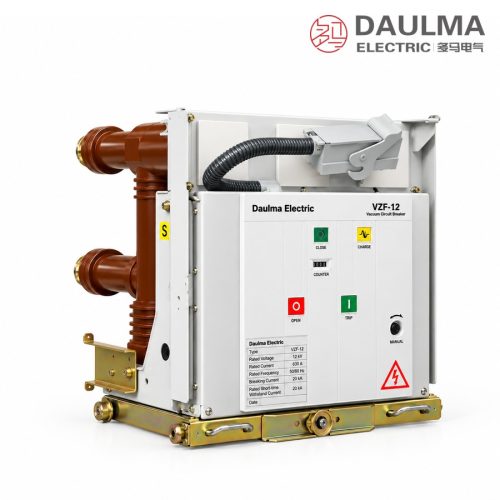
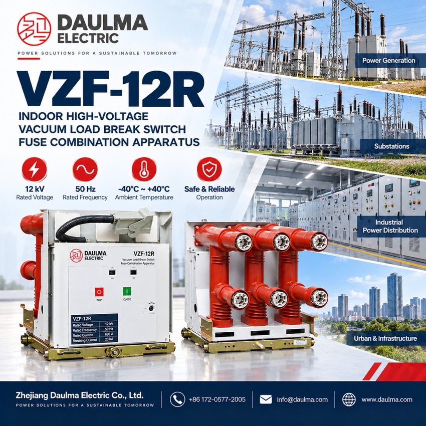
The VZF-12R is a 12 kV three-phase 50 Hz indoor vacuum load break switch and switch-fuse combination unit, centre-mounted with solid epoxy embedded poles for armoured metal-enclosed switchgear. The switch makes, carries and breaks load current (630 A, 20 kA short-time); in the combination unit the back-up fuse clears faults up to 50 kA, with 3150 A rated transfer current.
Product Display
Model Designation
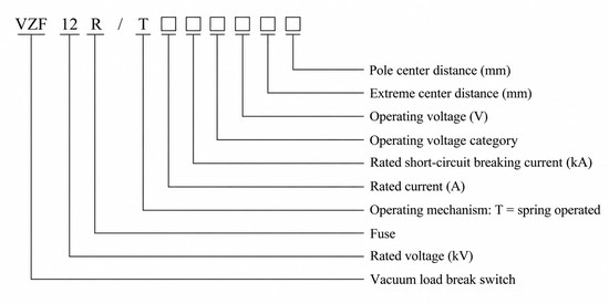
Type code: VZF 12 R / T □ □ □ □ □ □
- VZF — vacuum load break switch
- 12 — rated voltage (kV)
- R — fuse-equipped combination version
- T — spring operating mechanism
- First □ — rated current (A)
- Second □ — rated short-circuit breaking current (kA)
- Third □ — operating-voltage category and control voltage (V)
- Fourth □ — pole spacing / phase spacing (mm)
Examples: VZF12/T630-20 is the 12 kV vacuum load break switch with 630 A rated current and 20 kA short-time withstand; VZF-12/T125-50 is the load break switch – fuse combination unit with a 125 A fuse and 50 kA fuse breaking current.
Service Conditions
- Ambient temperature: −40 °C to +40 °C
- Altitude: not exceeding 1500 m
- Relative humidity: daily average ≤ 95%, monthly average ≤ 90%
- Vapour pressure: daily average ≤ 2.2 × 10⁻³ MPa, monthly average ≤ 1.8 × 10⁻³ MPa
- Seismic intensity: not exceeding degree 8
- Environment free from dripping water, fire or explosion hazard, corrosive gas and violent vibration
Construction
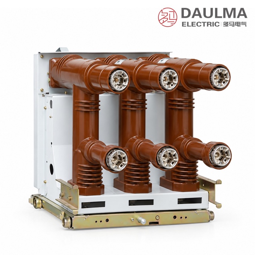
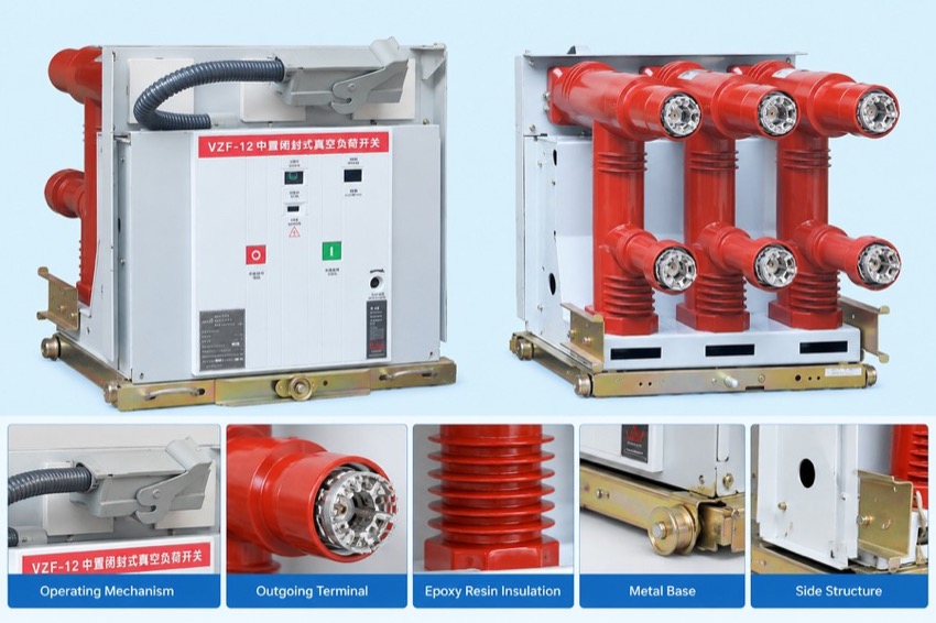
The three switch poles are encapsulated in epoxy resin by APG casting, forming a compact centre-mounted unit that is insensitive to dust and moisture and needs no special maintenance of the live parts. Load current is interrupted in sealed vacuum interrupters driven by a spring energy-storage mechanism (T) that provides stored-energy closing and opening with defined closed, open and earthed positions.
In the combination version the high-voltage fuses sit in dedicated compartments above the switch poles and are mechanically coupled to them: a fuse striker releases the trip of the associated switch pole so that all three phases open on single-phase fuse operation. The 3150 A rated transfer current coordinates the duty handover between switch and fuse, and interlocks prevent unsafe operation of the switch-fuse set.
Technical Data
| No. | Item | Unit | VZF12/T630-20 (vacuum load break switch) |
VZF-12/T125-50 (switch-fuse combination) |
|---|---|---|---|---|
| 1 | Rated voltage | kV | 12 | 12 |
| 2 | 1 min power-frequency withstand voltage (phase-to-phase / to earth) | kV | 42 | 42 |
| 3 | Lightning impulse withstand voltage (phase-to-phase / to earth) | kV | 75 | 75 |
| 4 | Rated current | A | 630 | 125 (fuse) |
| 5 | Rated short-circuit breaking current | kA | — | 50 (by fuse) |
| 6 | Rated short-time withstand current | kA | 20 | — |
| 7 | Rated peak withstand current | kA | 50 | — |
| 8 | Rated short-circuit making current (peak) | kA | 50 | — |
| 9 | Rated cable charging breaking current | A | 16 | — |
| 10 | Rated transfer current | A | — | 3150 |
| 11 | Breaking of no-load transformer | kVA | 1250 | — |
| 12 | Mechanical life | operations | 10000 | — |
| 13 | Partial discharge | pC | ≤ 5 | — |
Standards
The load break switch is designed and tested to GB 3804 for AC high-voltage load switches, and the switch-fuse combination unit to GB 16926 for AC high-voltage load switch – fuse combination units.
Installation & Dimensions
Installation Diagram
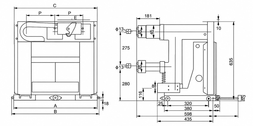
The epoxy embedded-pole unit bolts to the cubicle frame on its base rails; primary terminals connect to busbar or cable lugs and fuses, where fitted, insert into the compartments above the switch poles. The secondary loop (spring motor, auxiliary and anti-pumping contacts, fuse-striker trip) wires to the cubicle terminal block, and earth-switch and mechanism interlocks must be proved before commissioning.
| Outline dimension | Value (mm) |
|---|---|
| Overall height | 635 |
| Overall depth (side view) | 435 |
| Base mounting span | 320 380 598 |
| Vertical pole spacing | 275 280 |
| Mounting hole diameter | 4 × Ø 13 |