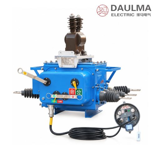
Product Overview
The ZW20Z-12 is a 12 kV 50 Hz outdoor pole-mounted vacuum circuit breaker combining vacuum arc extinction with SF6 gas insulation in a sealed, explosion-proof enclosure derived from the Toshiba VSP5 structure. As an improved ZW20-12 it adds overcurrent protection, spring-energy indicators and aviation plugs for secondary wiring, so it pairs with intelligent controllers for reclosing and distribution automation; rated currents of 630 A and 1250 A pair with breaking capacities from 12.5 to 25 kA.
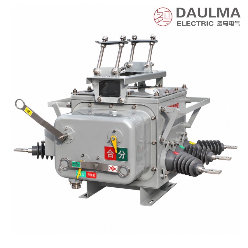
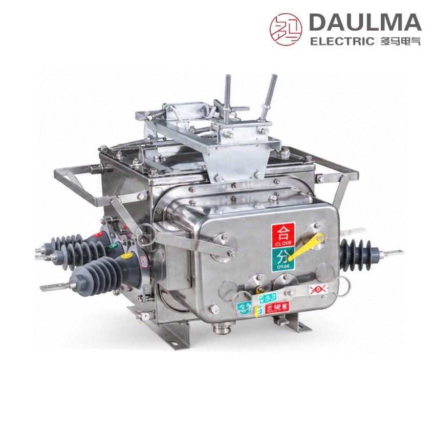
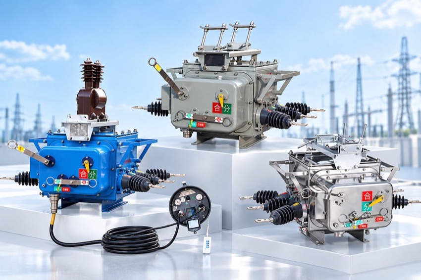
Product Display
Model Designation
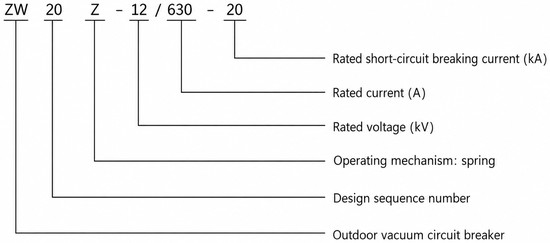
Model format: ZW 20 Z − 12 / 630 − 20
- ZW — Outdoor vacuum circuit breaker
- 20 — Design sequence number
- Z — Spring operating mechanism
- 12 — Rated voltage (kV)
- 630 — Rated current (A)
- 20 — Rated short-circuit breaking current (kA)
Service Conditions
- Ambient temperature: −40 °C to +40 °C
- Altitude: not exceeding 3000 m (higher altitude on request with a correspondingly higher rated insulation level)
- Relative humidity: daily average ≤ 95%, monthly average ≤ 90%
- Wind pressure: not exceeding 700 Pa (equivalent to wind speed 34 m/s)
- Neutral earthing: solidly earthed, earthed via arc-suppression coil, or earthed via low resistance
- Installation environment free from explosive or severely polluting gas and chemical corrosion
Construction
The ZW20Z-12 pairs a compact miniaturised spring mechanism with direct-chain drive and multi-stage tripping with an internal-collecting / external-expanding bracelet main circuit for low contact resistance and low temperature rise. The sealed, explosion-proof enclosure based on the Toshiba VSP5 structure keeps the internal SF6 fully isolated from the environment, guaranteeing zero leakage and maintenance-free operation.
Overcurrent protection, mechanism spring-energy indicators and aviation-plug secondary links allow straightforward integration with intelligent controllers and reclosing schemes for distribution automation. Sealed lead-out bushings and the robust enclosure hold stable service from -40 °C to +40 °C and at altitudes up to 3000 m.
Technical Data
| Item | Unit | Value |
|---|---|---|
| Rated Voltage | kV | 12 |
| Rated Frequency | Hz | 50 |
| Rated Current | A | 630 1250 |
| Rated Short-Circuit Breaking Current | kA | 12.5 16 20 25 |
| Rated Peak Withstand Current (peak) | kA | 31.5 40 50 63 |
| Rated Short-Time Withstand Current (4 s) | kA | 12.5 16 20 25 |
| Rated Short-Circuit Making Current (peak) | kA | 31.5 40 50 63 |
| Mechanical Life | Times | 10000 |
| Rated-Current Breaking Times | Times | 10000 |
| Rated Short-Circuit Breaking Times | Times | 30 |
| Power-Frequency Withstand Voltage (1 min, phase-phase / earth / open) | kV | 42 |
| Lightning Impulse Withstand Voltage (peak) | kV | 75 |
| Secondary Circuit 1 min Power-Frequency Withstand Voltage | kV | 2 |
| Net Weight | kg | 140 |
Standards
Manufactured and tested in accordance with IEC and GB standards for high-voltage AC circuit breakers, including IEC 62271-100 and GB 1984.
Installation & Dimensions
Installation Diagram
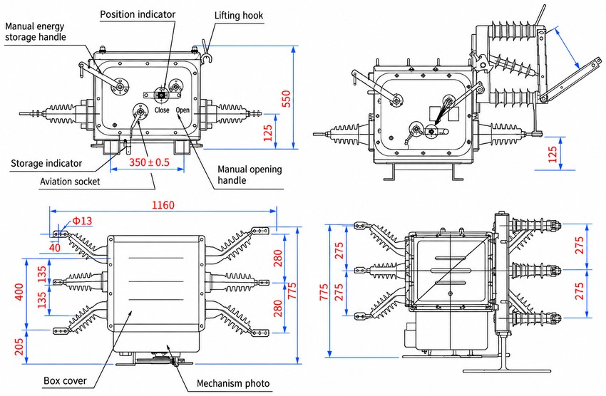
The breaker is designed for standard pole mounting with clear phase spacing and secure anchoring points to ensure mechanical stability under wind (up to 700 Pa) and ice loading; the outline and mounting dimensions are given in the drawing.
| Dimension | Value (mm) |
|---|---|
| Overall width (across outgoing bushings) | 1160 |
| Overall height | 775 |
| Mechanism box height | 550 |
| Lower section height | 125 |
| Aviation-socket centre spacing | 350 ± 0.5 |
| Phase-to-phase spacing (front view) | 135 / 135 |
| Phase-to-phase spacing (side view) | 275 / 275 |
| Base mounting height | 205 |
| Bushing terminal hole diameter | φ13 |