Product Overview
The JSGW-0.5 dry-type low-voltage potential transformer is an indoor three-phase five-leg voltage transformer designed for voltage measurement, electric energy metering, and relay protection applications. It provides stable voltage signals for measuring instruments, energy meters, and protection devices in 50Hz AC power systems.
The JSGW-0.5, also referred to as JSGW-0.5F in some specifications, uses a dry-type insulated structure with a three-phase five-leg magnetic core. It includes main secondary windings and auxiliary secondary windings for open-delta connection, making it suitable for voltage monitoring, metering, insulation supervision, and protection signal acquisition in indoor electrical systems.
Product Type
| Item | Specification |
|---|---|
| Product name | Three-Phase Five-Leg Dry-Type Low Voltage Potential Transformer |
| Model series | JSGW-0.5 / JSGW-0.5F |
| Product structure | Indoor dry-type insulated voltage transformer, three-phase five-leg design |
| Rated frequency | 50Hz |
| Typical voltage ratio | 380/√3 / 100/√3 / 100/3; 500/√3 / 100/√3 / 100/3 |
| Secondary winding | Main secondary winding and auxiliary secondary winding |
| Installation location | Indoor |
| Typical applications | Voltage measurement, electric energy metering, relay protection, open-delta voltage monitoring |
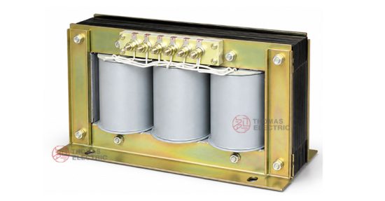
Product Display


Main Applications
- Indoor AC power systems requiring three-phase voltage measurement
- Electric energy metering and power monitoring circuits
- Relay protection circuits requiring isolated voltage signals
- Open-delta residual voltage monitoring circuits
- Low-voltage switchgear, metering panels, and protection cabinets
- Voltage signal acquisition for monitoring instruments and protection devices
- Systems requiring auxiliary secondary windings for insulation monitoring or abnormal voltage detection
Key Technical Features
- Three-phase five-leg design: The magnetic core includes three central columns and two outer columns, supporting three-phase voltage transformation and auxiliary residual voltage output.
- Dry-type insulated structure: Suitable for indoor electrical systems without oil insulation.
- Auxiliary secondary winding: Supports open-delta connection for residual voltage or protection-related monitoring.
- Standard secondary output: Provides 100/√3 and 100/3 voltage outputs according to the selected winding configuration.
- Multiple rated outputs: Rated outputs are available for 0.5, 1, and 3 accuracy classes according to metering or protection requirements.
- Indoor fixed installation: Compact structure for installation inside switchgear, metering cabinets, and protection panels.
Working Principle
The JSGW-0.5 voltage transformer operates according to electromagnetic induction. The primary winding is connected to the measured three-phase voltage circuit, and the secondary windings output proportional reduced voltage signals for meters, relays, and monitoring devices. The auxiliary secondary winding can be connected in an open-delta circuit to provide residual voltage signals for insulation monitoring or relay protection functions.
Model Designation

The model code can be interpreted as follows:
| Code | Meaning |
|---|---|
| J | Voltage transformer / potential transformer |
| S | Three-phase structure |
| G | Five-leg magnetic core |
| W | Dry-type design |
| 0.5 | Voltage grade / product voltage class code |
| F | Optional extended design code where applicable |
Technical Data
| Item | Specification |
|---|---|
| Model | JSGW-0.5 / JSGW-0.5F |
| Rated frequency | 50Hz |
| Rated voltage ratio | 380/√3 / 100/√3 / 100/3; 500/√3 / 100/√3 / 100/3 |
| Main secondary voltage | 100/√3V |
| Auxiliary secondary voltage | 100/3V |
| Accuracy class | 0.5, 1, 3 according to rated output and application |
| Rated output | 50VA / 80VA / 250VA according to accuracy class |
| Maximum rated output | 340VA |
| Insulation level | 0.5/3kV according to catalogue data |
| Core structure | Three-phase five-leg external iron core |
| Installation location | Indoor |
| Applicable standards | IEC 60044-2, GB 1207-2006; project-specific requirements can be confirmed by agreement |
Rated Voltage Ratio, Accuracy and Output Reference
| Rated
Voltage Ratio |
Frequency
(Hz) |
Output 0.5
Class (VA) |
Output 1
Class (VA) |
Output 3
Class (VA) |
Max. Output
(VA) |
Insulation
Level (kV) |
|---|---|---|---|---|---|---|
| 380/√3 / 100/√3 / 100/3 | 50 | 50 | 80 | 250 | 340 | 0.5/3 |
| 500/√3 / 100/√3 / 100/3 | 50 | 50 | 80 | 250 | 340 | 0.5/3 |
Note: Special voltage ratios, output ratings, and installation dimensions can be confirmed by technical agreement before ordering.
Service Conditions
- Installation location: indoor
- Rated frequency: 50Hz AC
- The product should be installed in a controlled indoor electrical environment.
- The installation environment should be free from severe vibration, corrosive gas, explosive medium, conductive dust, and heavy pollution.
- For special altitude, humidity, temperature, pollution level, or cabinet layout requirements, technical confirmation is recommended before ordering.
Standards & Compliance
The JSGW-0.5 dry-type low-voltage potential transformer can be supplied according to IEC 60044-2, GB 1207-2006, and customer-specific technical requirements. Final standards, routine test items, nameplate data, and acceptance documents should be confirmed in the technical agreement.
Installation & Dimensions

The JSGW-0.5 series adopts an indoor fixed installation structure. The three-phase primary terminals, main secondary terminals, and auxiliary secondary terminals should be wired according to the approved principle diagram. Final outline and mounting dimensions should be confirmed according to the approved drawing before cabinet design or batch ordering.
Terminal Marking Reference

| Terminal Group | Marking | Function |
|---|---|---|
| Primary winding | A, B, C, 0 | Three-phase primary voltage input |
| Main secondary winding | a, b, c, 0 | Voltage output for measurement, metering, and protection |
| Auxiliary secondary winding | ad, xd | Open-delta / residual voltage monitoring output |
Connection & Wiring Notes
- Connect primary terminals according to the marked symbols A, B, C, and 0.
- Connect main secondary terminals according to a, b, c, and 0 for measurement or metering circuits.
- Connect auxiliary secondary terminals ad and xd according to the open-delta protection or monitoring circuit.
- Confirm the voltage ratio, rated output, accuracy class, and wiring diagram before energizing.
- The secondary winding must not be short-circuited when voltage is applied to the primary winding.
- Secondary wiring, grounding, and terminal protection should comply with project specifications and local electrical regulations.
Installation & Safety Notes
- Confirm the product model, insulation level, voltage ratio, number of cores, output, and accuracy class before installation.
- Install the transformer in an indoor cabinet or controlled electrical room according to the approved mounting drawing.
- Check that all primary, secondary, and auxiliary terminals are correctly identified before wiring.
- Do not operate the transformer beyond its rated output or maximum rated output.
- Installation, testing, and maintenance should be performed by qualified electrical personnel.
Selection Guidelines
- Confirm application: Determine whether the transformer is used for voltage measurement, electric energy metering, relay protection, or residual voltage monitoring.
- Confirm voltage ratio: Select the primary and secondary voltage ratio according to the three-phase system and connected instruments.
- Confirm auxiliary winding: Use the auxiliary secondary winding when open-delta residual voltage output is required.
- Select accuracy class: Use the required accuracy class according to metering, monitoring, or protection application.
- Check rated output: The connected burden of meters, relays, instruments, and wiring should not exceed the rated output.
- Confirm installation dimensions: Check the outline drawing, terminal position, and cabinet clearance before production or batch installation.