Product Overview
The LDJ-10Q / LDJ-10/210-L(Y) current transformer is an indoor, epoxy resin cast, fully enclosed current transformer designed for medium-voltage switchgear applications. It is especially suitable for KYN handcart-type switchgear and is used for current measurement, electric energy metering, feeder monitoring, and relay protection in AC power systems with rated frequency of 50Hz or 60Hz.
For international projects, this product can be specified for 10kV, 11kV, and 12kV medium-voltage systems using 12kV-class insulation coordination. The standard insulation level is 12/42/75kV. One of the primary lead-out terminals is designed with a terminal/contact box structure, making the product suitable for handcart switchgear connection and compact cabinet integration.
Product Type
| Item | Specification |
|---|---|
| Product name | Indoor Epoxy Resin Cast Fully Enclosed Current Transformer |
| Model series | LDJ-10Q / LDJ-10/210-L(Y) |
| Product structure | Indoor, fully enclosed, epoxy resin cast, through-type current transformer |
| Switchgear application | KYN handcart-type switchgear and indoor medium-voltage cabinets |
| Voltage class | 10kV, 11kV, and 12kV medium-voltage systems |
| Highest voltage for equipment | 12kV class |
| Rated insulation level | 12/42/75kV |
| Rated frequency | 50Hz / 60Hz |
| Rated secondary current | 5A or 1A; 2A can be confirmed for special requirements |
| Power factor of burden | cosφ = 0.8 lagging |
| Typical applications | Current measurement, energy metering, relay protection, feeder monitoring |
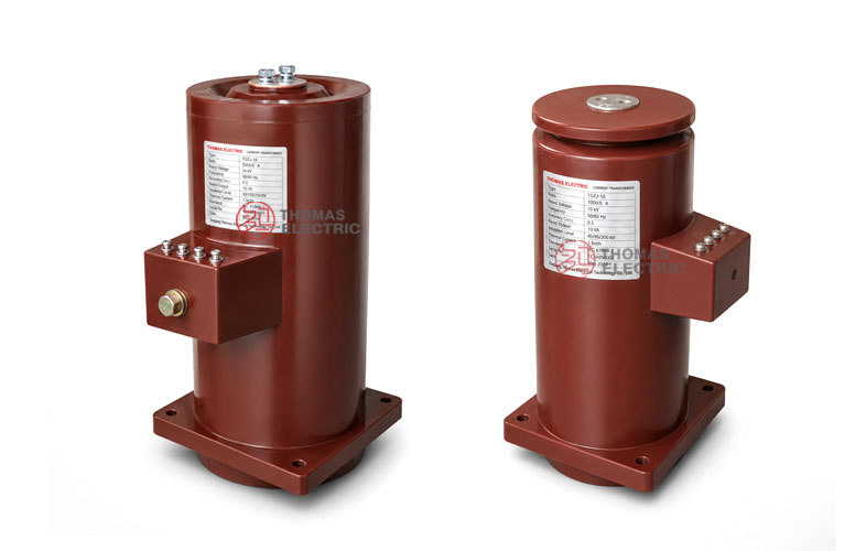
Product Display
 Current Transformer, KYN Handcart Switchgear Thomas Electric")
 Current Transformer, KYN Handcart Switchgear Thomas Electric")
Applications
- 10kV, 11kV, and 12kV indoor medium-voltage distribution systems
- KYN handcart-type switchgear and metal-clad switchgear
- Current measurement and electric energy metering circuits
- Relay protection and feeder monitoring circuits
- Incoming feeder panels, outgoing feeder panels, and distribution switchboards
- Medium-voltage cabinets requiring one primary terminal with terminal/contact box structure
Features
- Designed for KYN switchgear: The product structure is suitable for KYN handcart-type switchgear and compact indoor cabinet layouts.
- Fully enclosed epoxy casting: The epoxy resin cast body provides insulation strength, moisture resistance, and mechanical stability.
- Primary terminal box structure: One primary lead-out terminal is equipped with a terminal/contact box arrangement for switchgear connection.
- Measurement and protection use: Accuracy combinations can support metering classes and 10P10 protection applications.
- Flexible secondary current: 5A and 1A secondary outputs are available, and 2A can be confirmed for special project requirements.
- International voltage expression: Suitable for 10kV, 11kV, and 12kV applications with 12/42/75kV insulation level.
Working Principle
The LDJ-10/210-L(Y) current transformer operates according to electromagnetic induction. The primary current generates magnetic flux in the core, and the secondary winding outputs a proportional current signal to connected meters, protection relays, or monitoring devices. The epoxy resin casting body provides electrical insulation between the medium-voltage primary circuit and the low-voltage secondary circuit.
For metering circuits, the transformer should maintain the specified ratio accuracy and phase displacement under the rated burden. For relay protection circuits, the protection winding should provide a reliable current signal under fault conditions and coordinate with the protection relay setting, rated burden, and system short-circuit level.
Model Designation
 Current Transformer, KYN Handcart Switchgear Thomas Electric")
The model designation is used to identify the product structure, reinforced insulation option, voltage class, and special handcart switchgear layout.
| Code | Meaning |
|---|---|
| L | Current transformer |
| D | Through-type / special switchgear current transformer structure |
| J | Indoor epoxy resin cast insulation structure |
| 10 | Voltage class identification; used for 10kV systems and 12kV-class insulation coordination |
| Q | Reinforced insulation or special structure variant when specified |
| 210 | Structural dimension / window or installation design code |
| L | Special layout version for handcart switchgear application |
Model coverage: This page covers LDJ-10/210-L(Y), LDJ-10Q, and LDJ-10/210-L(Y)(Y). Final selection should be confirmed by current ratio, accuracy class, rated output, secondary current, switchgear layout, primary terminal box arrangement, and approved drawing.
Technical Data
| Item | Specification |
|---|---|
| Rated voltage class | 10kV / 11kV / 12kV medium-voltage systems |
| Highest voltage for equipment | 12kV class |
| Rated insulation level | 12/42/75kV |
| Rated frequency | 50Hz / 60Hz |
| Rated primary current | 5A to 1250A reference range; 1500A to 3150A can be confirmed by specification and drawing |
| Rated secondary current | 5A or 1A; 2A available by special confirmation |
| Accuracy class combination | 0.2S / 10P10, 0.2 / 10P10, 0.5 / 10P10, 0.5S / 10P10 |
| Rated output | 10VA / 15VA / 20VA / 25VA according to current ratio and core configuration |
| Power factor of burden | cosφ = 0.8 lagging |
| Creepage distance | Greater than 530mm reference |
| Ambient temperature | -5°C to +40°C standard service range; project-specific temperature can be confirmed |
| Insulation medium | Epoxy resin casting insulation |
| Applicable standard | IEC 61869-1 / IEC 61869-2; IEC 60044-1 can be referenced for legacy specification |
Terminal Marking
 Current Transformer, KYN Handcart Switchgear Thomas Electric")
The LDJ-10/210-L(Y) series is designed with a special primary lead-out arrangement for handcart switchgear. One primary terminal can be equipped with a terminal/contact box structure. Secondary terminal configuration depends on the selected metering and protection cores.
| Terminal Marking | Function | Application Note |
|---|---|---|
| P1 / P2 | Primary terminals | The reference primary current direction is normally defined from P1 to P2. |
| Primary terminal box | Primary lead-out structure | One primary lead-out terminal can include a terminal/contact box for handcart switchgear connection. |
| 1S1 / 1S2 | First secondary winding | Usually used for metering, measurement, or the first specified secondary core. |
| 2S1 / 2S2 | Second secondary winding | Usually used for relay protection or an additional secondary circuit when required. |
Terminal markings follow standard current transformer polarity conventions. Correct terminal identification shall be observed to ensure metering accuracy, relay protection performance, and safe maintenance. The secondary circuit must not be open-circuited when the primary circuit is energized.
Selection Table
| Type | Rated
Primary Current (A) |
Accuracy
Class Combination |
Rated
Output (VA) |
Short-Time
Thermal Current (kA/1s) |
Rated
Dynamic Current (kA) |
|---|---|---|---|---|---|
| LDJ-10/210-L LDJ-10/210-L(Y) |
5 | 0.2 / 5P10 0.2S / 5P10 0.5 / 5P10 0.2 / 10P10 0.2S / 10P10 0.5 / 10P10 |
10 / 15 | 0.3 | 0.75 |
| 10 | 0.6 | 1.5 | |||
| 15 | 0.9 | 2.25 | |||
| 20 | 1.2 | 3 | |||
| 30 | 1.8 | 4.5 | |||
| 50 | 3 | 7.5 | |||
| 75 | 4.5 | 11.25 | |||
| 100 | 6.5 | 16.25 | |||
| 150 | 10 | 25 | |||
| 200 | 13 | 32.5 | |||
| 300 | 20 | 50 | |||
| 400 | 26 | 65 | |||
| 500 | 15 / 15 | 32.5 | 82 | ||
| 600 | 40 | 100 |
Note: The table is for preliminary engineering selection. Final model, current ratio, secondary current, accuracy class, rated output, short-time thermal current, dynamic current, insulation level, terminal arrangement, and test requirements shall be confirmed according to the approved drawing, nameplate, and factory test report.
Service Conditions
- Installation location: indoor medium-voltage switchgear
- System voltage: 10kV, 11kV, or 12kV class
- Rated frequency: 50Hz / 60Hz
- Rated insulation level: 12/42/75kV
- Altitude: not exceeding 1000m under standard service conditions unless otherwise specified
- Ambient temperature: -5°C to +40°C standard reference range
- Power system grounding: suitable for non-effectively grounded neutral systems according to project configuration
- The installation site should be free from severe pollution, corrosive gas, explosive medium, heavy conductive dust, and abnormal condensation.
Standards and Compliance
The LDJ-10Q / LDJ-10/210-L(Y) current transformer can be supplied according to IEC 61869-1 and IEC 61869-2. IEC 60044-1 can be referenced for legacy project specifications. Routine tests, dielectric tests, polarity verification, ratio test, accuracy test, insulation resistance, and partial discharge requirements should be confirmed according to the final technical agreement.
Installation and Dimensions
 Current Transformer, KYN Handcart Switchgear Thomas Electric")
The LDJ-10/210-L(Y) series is designed for KYN handcart-type switchgear. The primary terminal box, P1/P2 direction, secondary terminal layout, installation base, and phase-to-ground clearance shall be confirmed by the approved outline drawing before cabinet design or batch production.
Outline Data
| Item | Selection Note |
|---|---|
| Mechanical structure | Indoor epoxy resin cast fully enclosed through-type structure |
| Switchgear application | KYN handcart-type switchgear |
| Primary terminals | P1 / P2 terminal arrangement with one terminal/contact box structure |
| Secondary terminals | 1S1 / 1S2 and optional 2S1 / 2S2 according to secondary core configuration |
| Drawing confirmation | Final outline, terminal direction, mounting dimensions, and switchgear matching shall be confirmed before production |
Safety Notes
- Confirm the model, voltage class, current ratio, secondary current, accuracy class, burden, insulation level, and short-circuit withstand requirement before installation.
- Check KYN switchgear matching, primary terminal box location, handcart clearance, phase clearance, and maintenance access before assembly.
- Connect primary and secondary terminals according to terminal markings and the project wiring diagram.
- The secondary circuit of a current transformer must not be left open when the primary circuit is energized.
- During meter or relay maintenance, short-circuit the CT secondary circuit before disconnecting any secondary wiring.
- Secondary grounding shall follow the project specification and local electrical safety requirements.
- Installation and maintenance shall be performed by qualified medium-voltage electrical personnel.
Ordering Info
Please provide the following information when ordering or requesting a quotation:
- Product model: LDJ-10Q or LDJ-10/210-L(Y)
- System voltage: 10kV, 11kV, or 12kV
- Rated primary current / current transformation ratio
- Rated secondary current: 1A, 2A, or 5A
- Accuracy class combination and rated output for each secondary core
- Protection class and relay protection requirement if applicable
- Short-circuit withstand requirement: one-second thermal current and dynamic current
- Switchgear type: KYN handcart cabinet or other cabinet structure
- Primary terminal box direction, terminal layout, and required outline drawing
- Quantity, labeling, certificates, routine test reports, and packaging requirements
- Special customized current ratio, secondary winding, burden, or terminal arrangement requirements
Selection Tips
- Confirm switchgear type: This model is especially suitable for KYN handcart-type switchgear, so cabinet matching should be checked first.
- Confirm voltage level: Use 12kV-class insulation coordination for 10kV, 11kV, or 12kV systems.
- Confirm current ratio: Select the primary current according to feeder load, metering range, and relay protection setting range.
- Confirm secondary current: Select 5A or 1A according to meters, relays, cable length, and burden calculation. 2A can be confirmed for special requirements.
- Check rated burden: The total burden of meters, relays, and secondary cables must not exceed the rated output of each secondary core.
- Verify withstand rating: Check one-second thermal current and dynamic current against the switchgear fault-current level.
- Confirm drawings: Verify the primary terminal box, terminal direction, mounting dimensions, and cabinet clearances before production.