Product Overview
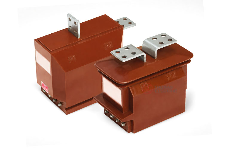
The LFSQ-10 current transformer is an indoor single-phase epoxy resin cast current transformer with a reinforced fully enclosed structure. It is designed for current measurement, electric energy metering, feeder monitoring, and relay protection in IEC-oriented medium-voltage systems, including 10kV, 11kV, and 12kV indoor switchgear applications.
Compared with standard indoor cast-resin current transformers, the LFSQ-10 series is designed with reinforced insulation and enhanced thermal and dynamic stability. Its primary winding, secondary winding, and magnetic core are encapsulated in epoxy resin casting insulation. The fully enclosed body provides moisture resistance, anti-pollution performance, compact installation, and reliable operation under indoor switchgear service conditions. The product is suitable for cart switchboard, handcart switchgear, metal-clad switchgear, and compact medium-voltage distribution cabinets.
Product Type
| Item | Specification |
|---|---|
| Product name | Indoor Reinforced Epoxy Resin Cast Current Transformer |
| Model series | LFSQ-10 |
| Product structure | Indoor single-phase, reinforced, totally enclosed, epoxy resin cast current transformer |
| Voltage class | 10kV, 11kV, and 12kV medium-voltage systems |
| Highest voltage for equipment | 12kV class |
| Rated insulation level | 12/42/75kV |
| Rated frequency | 50Hz / 60Hz |
| Rated secondary current | 5A or 1A according to project requirement |
| Power factor of burden | 0.8 lagging reference |
| Installation location | Indoor cart switchboard, handcart switchgear, and medium-voltage distribution equipment |
| Applicable standard | IEC 61869-1 / IEC 61869-2; IEC 60044-1 can be referenced for legacy projects |
Product Display


Main Applications
- 10kV, 11kV, and 12kV indoor medium-voltage distribution systems
- Cart switchboard, handcart switchgear, and metal-clad switchgear
- Current measurement and electric energy metering circuits
- Relay protection circuits requiring 10P-class protection performance
- Industrial substations, utility distribution rooms, and commercial medium-voltage cabinets
- Indoor installations requiring reinforced insulation and higher thermal / dynamic stability
Key Technical Features
- International voltage class: Suitable for 10kV, 11kV, and 12kV systems, with IEC-style 12/42/75kV insulation level for 12kV-class switchgear.
- Reinforced cast-resin insulation: The primary winding, secondary winding, and core are fully encapsulated in epoxy resin to improve insulation strength and moisture resistance.
- Higher thermal and dynamic stability: Peak and thermal stability are designed for higher withstand requirements compared with standard indoor CTs of similar structure.
- Totally enclosed structure: The sealed resin body improves anti-pollution performance and supports easier surface cleaning in indoor switchgear environments.
- Flexible mounting direction: The compact and lightweight structure supports installation at different positions and directions according to cabinet layout.
- Protection and measurement use: Accuracy combinations can support measurement, metering, and 10P relay protection applications.
Working Principle
The LFSQ-10 current transformer operates according to electromagnetic induction. Primary current flowing through the primary winding generates magnetic flux in the magnetic core. The secondary winding then outputs a proportional current signal to connected meters, protection relays, or monitoring devices. The epoxy resin casting body provides electrical insulation between the medium-voltage primary circuit and the low-voltage secondary circuit.
For measurement and metering circuits, the CT should maintain the specified ratio and phase accuracy under the rated burden. For protection circuits, the 10P winding must provide a reliable current signal during fault-current conditions and coordinate with relay settings, burden, and accuracy limit factor.
Model Designation

The model designation identifies the product type, enclosed structure, switchgear application, reinforced insulation, and voltage class.
| Code | Meaning |
|---|---|
| L | Current transformer |
| F | Totally enclosed type |
| S | Used for cart switchboard / handcart switchgear application |
| Q | Reinforced design / reinforced insulation configuration |
| 10 | Voltage class identification; applicable to 10kV systems and IEC 12kV-class insulation coordination for 10kV, 11kV, and 12kV projects |
Technical Data
| Item | Specification |
|---|---|
| Rated voltage class | 10kV / 11kV / 12kV medium-voltage systems |
| Highest voltage for equipment | 12kV class |
| Rated insulation level | 12/42/75kV |
| Rated frequency | 50Hz / 60Hz |
| Rated primary current | 5A to 1500A reference range; customized ratios available according to project requirement |
| Rated secondary current | 5A or 1A |
| Accuracy class combination | 0.2 / 0.2, 0.2 / 0.5, 0.2 / 10P, 0.5 / 10P or project-specific combinations |
| Rated output | 10VA / 15VA / 20VA / 30VA / 40VA according to current ratio and accuracy class |
| Power factor of burden | 0.8 lagging reference |
| Protection accuracy class | 10P or project-specific protection class |
| Insulation medium | Epoxy resin casting insulation |
| Installation method | Indoor mounting with base plate and M10 mounting holes according to approved drawing |
| Applicable standard | IEC 61869-1 / IEC 61869-2; IEC 60044-1 can be referenced for legacy specification |
Windings & Terminal Marking
The LFSQ-10 current transformer can be supplied with measurement, metering, protection, or combined secondary winding configurations. The final terminal arrangement shall be confirmed according to the selected accuracy combination and approved wiring diagram.
| Terminal Marking | Function | Application Note |
|---|---|---|
| P1 / P2 | Primary terminals | The reference primary current direction is normally defined from P1 to P2. |
| 1S1 / 1S2 | First secondary winding | Usually used for measurement, metering, or the first specified secondary core. |
| 2S1 / 2S2 | Second secondary winding | Usually used for relay protection or an additional secondary circuit when required. |
| Secondary terminal cover | Secondary wiring protection | Terminal cover supports safer wiring inspection and reduces accidental contact risk. |
Terminal markings follow standard CT polarity conventions. Correct terminal identification shall be observed to ensure metering accuracy, relay direction judgment, and protection performance. The secondary circuit must not be open-circuited when the primary circuit is energized.
Rated Current, Accuracy and Short-Circuit Withstand Reference
| Rated
Primary Current (A) |
Accuracy
Class Combination |
Rated
Output 0.2 (VA) |
Rated
Output 0.5 (VA) |
Rated
Output 10P (VA) |
Short-Time
Thermal Current |
Rated
Dynamic Current |
|---|---|---|---|---|---|---|
| 5, 10 | 0.2 / 0.2 0.2 / 0.5 0.2 / 10P 0.5 / 10P |
10 | 10 | 15 | 150 × I1n | 2.5 × I1n |
| 15–50 | 400 × I1n | 2.5 × I1n | ||||
| 75 | 32kA | 90kA | ||||
| 100–200 | 45kA | 100kA | ||||
| 300 | 63kA | 130kA | ||||
| 400, 500 | 10 / 20 / 30 | 20 | 30 | |||
| 600, 800,
1000–1500 |
20 / 30 / 40 | 30 / 40 | 40 |
Note: The table is for preliminary technical selection. If the secondary current is 1A, or if the requested parameters exceed the listed range, final current ratio, accuracy class, rated output, thermal current, dynamic current, terminal arrangement, and test requirements shall be confirmed by technical agreement.
10P Accuracy Limit Factor Reference
The LFSQ-10 protection winding selection should consider both rated output and connected secondary burden. The 10P accuracy limit factor curve is used to check whether the protection winding can maintain the required performance under a given burden and current ratio.
| Reference Curve | Applicable
Current Ratios |
Engineering
Use |
|---|---|---|
| LFSQ-10 10P curve | 5–200/5, 300/5, 400/5, 500/5, 600–1500/5 reference groups | Used for checking the relationship between 10P accuracy limit factor and secondary burden in relay protection circuits. |
Protection-class CT selection should verify the relay burden, cable resistance, rated output, current ratio, and 10P accuracy limit factor together. Final protection performance shall be confirmed according to the project relay setting and factory technical data.
Service Conditions
- Installation location: indoor medium-voltage switchgear
- System voltage: 10kV, 11kV, or 12kV class
- Rated frequency: 50Hz / 60Hz
- Rated insulation level: 12/42/75kV
- Altitude: not over 1000m under standard service conditions
- Ambient temperature: -5°C to +40°C
- Relative humidity: less than 85% at 20°C under reference conditions
- Environmental condition: suitable for indoor switchgear with humidity, condensation, and pollution control according to project requirements
- The installation environment should be free from severe vibration, corrosive gas, explosive medium, abnormal condensation, and heavy conductive dust.
Standards and Compliance
The LFSQ-10 current transformer can be supplied according to IEC 61869-1 and IEC 61869-2. IEC 60044-1 may be referenced for legacy project specifications. Routine tests, dielectric tests, polarity verification, ratio test, accuracy test, insulation resistance test, and partial discharge test should be confirmed according to the final technical agreement.
Installation and Dimensions

The LFSQ-10 series is designed for indoor cart switchboard and medium-voltage cabinet installation. The cast-resin body, base plate, M10 mounting holes, primary terminal arrangement, secondary terminal cover, terminal direction, and installation clearances shall be confirmed according to the approved outline drawing before switchgear design or batch production.
Available Structure and Overall Dimensions
| Item | Selection Note |
|---|---|
| Mechanical structure | Indoor reinforced, totally enclosed, epoxy resin cast current transformer |
| Switchgear application | Cart switchboard, handcart switchgear, and indoor medium-voltage cabinets |
| Primary terminals | P1 / P2 terminal arrangement according to approved drawing |
| Secondary terminals | 1S1 / 1S2 and optional 2S1 / 2S2 according to secondary core configuration |
| Mounting base | Base plate with four M10 mounting holes according to outline drawing |
| Drawing confirmation | Final outline, terminal direction, and mounting dimensions shall be confirmed before switchgear production |
Installation and Safety Notes
- Confirm the model, voltage class, current ratio, secondary current, accuracy class, burden, insulation level, and short-circuit withstand requirement before installation.
- Check switchgear mounting space, primary terminal connection, phase clearance, grounding arrangement, and maintenance access against the approved drawing.
- Connect primary and secondary terminals according to the terminal markings and project wiring diagram.
- The secondary circuit of a current transformer must not be left open when the primary circuit is energized.
- During meter or relay maintenance, short-circuit the CT secondary circuit before disconnecting any secondary wiring.
- Secondary grounding shall follow the project specification and local electrical safety requirements.
- Installation and maintenance shall be performed by qualified medium-voltage electrical personnel.
Ordering Information
Please provide the following information when ordering or requesting a quotation:
- Product model: LFSQ-10
- System voltage: 10kV, 11kV, or 12kV
- Rated primary current / current transformation ratio
- Rated secondary current: 1A or 5A
- Accuracy class combination and rated output for each secondary core
- Protection class and 10P accuracy limit factor requirement
- Short-circuit withstand requirement: short-time thermal current and dynamic current
- Insulation level and applicable IEC standard
- Switchgear type, installation layout, terminal direction, and required outline drawing
- Quantity, labeling, certificates, routine test reports, and packaging requirements
- Special customized current ratio, secondary winding, burden, or terminal arrangement requirements
Selection Guidelines
- Confirm voltage level: Select LFSQ-10 for indoor 10kV, 11kV, or 12kV switchgear using 12kV-class insulation coordination.
- Confirm reinforced insulation requirement: Use LFSQ-10 where reinforced insulation, higher thermal stability, or higher dynamic stability is required.
- Confirm current ratio: Select rated primary current according to feeder load, continuous operating current, and protection setting range.
- Confirm secondary current: Select 5A or 1A according to metering instruments, protection relays, cable length, and total burden calculation.
- Verify 10P performance: For protection circuits, check the 10P accuracy limit factor against connected burden using curve data or manufacturer technical data.
- Check short-circuit withstand: Ensure the short-time thermal current and rated dynamic current meet the switchgear fault-current level.
- Confirm drawings: Verify outline dimensions, terminal direction, mounting holes, and phase clearances before production.