Product Overview
Functional Definition
The LMZ3(D)-0.66 series current transformers are precision electromagnetic instruments designed for accurate current measurement, energy metering, and relay protection applications in low-voltage AC power systems. These transformers utilize electromagnetic induction principles to provide galvanically isolated secondary current signals proportional to primary current in electrical systems with rated voltage of 0.66 kV or below.
Key Ratings Snapshot
| Item | Specification (per order / nameplate) |
|---|---|
| System voltage class | 0.66 kV class (low-voltage distribution and switchgear applications) |
| Rated frequency | 50 Hz (60 Hz available upon request) |
| Rated secondary current | 5 A |
| Accuracy class | 0.5 (metering applications) |
| Rated burden | 10 VA to 30 VA (per type specification) |
| Burden power factor | cosφ = 0.8 (lagging) unless otherwise specified by the project standard |
| Insulation system | Epoxy resin cast insulation, fully enclosed structure |
| Installation environment | Indoor installation only |
| Applicable standards | IEC 60044-1; GB 1208-2006 |
| Product variants | LMZ1-0.66, LMZ2-0.66, LMZ3(D)-0.66 |
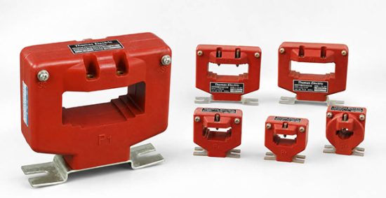
Product Shows
-0.66 Low-Voltage Current Transformer | Indoor Thomas Electric")
-0.66 Low-Voltage Current Transformer | Indoor Thomas Electric")
Working Principle
Operating on Faraday’s law of electromagnetic induction, the transformer features a loop-type (toroidal) magnetic core with the primary conductor passing through the core aperture and secondary windings uniformly wound around the core. The magnetic flux generated by primary current induces proportional voltage in the secondary winding, delivering standardized output current through connected burden. The epoxy resin casting provides complete insulation isolation between primary and secondary circuits.
System Application Position
- Low-Voltage Distribution: 0.66 kV switchgear and distribution panels
- Energy Metering: Electricity measurement systems for industrial and commercial applications
- Protection Circuits: Overcurrent protection schemes in low-voltage systems
- Motor Control Centers: Current monitoring in motor control and automation systems
- Power Quality Monitoring: Current measurement for power quality analysis equipment
Structural Form Overview
Epoxy resin cast construction with fully-enclosed design ensures superior insulation performance, moisture resistance, and mechanical strength. The loop-type (window-type) mounting configuration provides compact installation in constrained low-voltage switchgear environments. The busbar aperture design facilitates simple installation without primary circuit disconnection, allowing direct threading of busbars or cables through the transformer window.
Model Designation
-0.66 Low-Voltage Current Transformer | Indoor Thomas Electric")
Model Code Explanation
- L — Current transformer (CT)
- M — Window type (busbar through-hole design)
- Z — Cast-resin (epoxy) insulated, fully enclosed structure
- 1/2/3 — Design series (indicating current capacity range)
- (D) — Optional single-phase configuration indicator
- 0.66 — Voltage class (kV)
Series Differences
- LMZ1-0.66: Lower current range (200 A to 800 A), rated burden 10 VA
- LMZ2-0.66: Medium to high current range (1000 A to 4000 A), rated burden 15-30 VA
- LMZ3(D)-0.66: Specific configurations with dimensional optimization for compact installations
Service Conditions
The LMZ3(D)-0.66 series current transformers are designed for indoor operation under normal service conditions in low-voltage power systems.
- Installation environment: Indoor installation only
- Altitude: Not exceeding 1000 m above sea level (higher altitude shall be specified for engineering confirmation)
- Ambient temperature: −5 °C to +40 °C
- Relative humidity: Daily average ≤ 95%, monthly average ≤ 80% (at +20 °C reference)
- Environmental conditions: Free from corrosive gases or vapors; free from explosive or flammable media; no severe vibration, mechanical shock, or impact; no explosive dust
Construction
Construction Design
- Structure: Window type (loop type) for busbar or cable threading
- Insulation: Fully enclosed epoxy resin cast insulation
- Core: Loop-type (toroidal) magnetic core design
- Secondary winding: Uniformly wound around the magnetic core for consistent accuracy
- System: Integrated primary and secondary insulation system with complete galvanic isolation
The epoxy resin casting provides stable insulation properties and resistance to moisture, contamination, and aging for long-term indoor service. The window-type design eliminates the need for primary circuit disconnection during installation.
Windings & Terminal Marking
- Primary conductor: Busbar or cable passing through the window aperture (no fixed terminals)
- Secondary terminals: K / L (polarity marking as per standard convention)
Terminal markings follow standard CT polarity conventions. Under normal operating conditions, when primary current flows in the specified direction through the aperture, secondary current flows from K to L. Correct terminal identification shall be observed to ensure metering and protection performance.
Technical Data
This section provides selection-oriented technical data for the LMZ3(D)-0.66 series indoor, cast-resin current transformer used in 0.66 kV class AC systems (50 Hz / 60 Hz). Data shown below is intended for preliminary selection of current ratios, accuracy class, and rated burden.
Definitions: Rated primary current is the nominal current for which the transformer is designed. Rated output (VA) is the burden the transformer can supply while maintaining specified accuracy. Accuracy class defines the maximum permissible ratio error and phase displacement under specified conditions.
Data Reference
| Type | Rated Primary Current (A) |
Rated Secondary Current (A) | Accuracy Class | Rated Output (VA) |
|---|---|---|---|---|
| LMZ1-0.66 | 200, 300, 400, 600, 800 | 5 | 0.5 | 10 |
| LMZ2-0.66 | 1000, 1200, 1500 | 5 | 0.5 | 15 |
| LMZ2-0.66 | 2000, 2500, 3000 | 5 | 0.5 | 20 |
| LMZ2-0.66 | 4000 | 5 | 0.5 | 30 |
Standards & Normative References
| Standard | Title | Application |
|---|---|---|
| IEC 60044-1 | Instrument Transformers – Part 1: Current Transformers | International standard for CT design and testing |
| GB 1208-2006 | Current Transformers | National standard (aligned with IEC framework) |
| GB/T 20840.1 | Instrument Transformers – Part 1: General Requirements | General requirements reference |
| GB/T 20840.2 | Instrument Transformers – Part 2: Current Transformers | CT-specific requirements reference |
| IEC 60085 | Electrical Insulation – Thermal Evaluation | Insulation thermal evaluation reference |
Factory Testing Compliance
- Routine tests per applicable IEC/GB requirements (including polarity/marking verification, ratio verification, and accuracy verification per specified class and burden)
- Dielectric tests per insulation coordination requirements and applicable standard
- Visual and dimensional inspection including marking and workmanship conformity
- Type tests as required by the standard or project specification
Installation & Dimensions
- Outline dimensions and mounting details are provided in the dimensional drawings.
- The transformer shall be securely mounted using the designated fixing holes.
- Primary conductor (busbar or cable) shall pass through the window aperture with adequate clearance.
- Adequate clearance shall be maintained for insulation, heat dissipation, and maintenance access.
- Installation shall ensure the transformer orientation matches the design intent for optimal performance.
Outline Drawing
-0.66 Low-Voltage Current Transformer | Indoor Thomas Electric")
Overall Dimensions
| Type | A (mm) |
B (mm) |
C (mm) |
D (mm) |
E | F (mm) |
G (mm) |
K (mm) |
L (mm) |
W (mm) |
H (mm) |
|---|---|---|---|---|---|---|---|---|---|---|---|
| LMZ3D-0.66 B00-1500/5 | 131 | 86 | 48 | 43 | 2-M6 | 30 | 39 | 45 | 144 | 63 | 135 |
| LMZ3D-0.66 3000/5 | 187 | 130 | 90 | 62 | 2-M8 | 74 | 50 | 205 | 66 | 174 | — |
Safety Notes
- Secondary circuit must never be left open when the transformer is energized, as dangerous high voltage may appear across the secondary terminals.
- During inspection or maintenance, the secondary circuit shall be short-circuited before disconnecting any instruments.
- One point of the secondary circuit should be reliably grounded in accordance with applicable standards.
- All installation and maintenance work shall comply with local electrical safety regulations.
- Primary conductor installation shall ensure adequate clearance through the window aperture to prevent insulation damage.
Ordering Information
When placing an order, the required configuration shall be specified according to the local grid requirements, applicable standards, and project technical specification. The following parameters shall be clearly stated for technical confirmation and production release:
- Rated primary current / transformation ratio (e.g., 1000/5, 2000/5)
- Rated secondary current (5 A standard)
- Application and accuracy requirements (accuracy class 0.5 for metering)
- Rated burden (VA) based on connected load
- Frequency (50 Hz or 60 Hz)
- Quantity and delivery schedule
How to Select
Step 1: Determine rated primary current (Ip) based on circuit continuous current rating and expected operating range.
Step 2: Select appropriate product series (LMZ1 for lower currents, LMZ2 for higher currents) based on current magnitude.
Step 3: Confirm rated burden (VA) for secondary circuit based on connected meters and wiring losses. Total connected burden shall not exceed rated output.
Step 4: Verify dimensional constraints and mounting requirements for the installation location.
Step 5: Specify any special requirements (frequency, environmental conditions, certification requirements, documentation language).
If local utility or project requirements apply (e.g., specific test protocols, certification requirements, terminal arrangement, mounting constraints, documentation language, or required certificates), specify them at the ordering stage. Special configurations shall be confirmed by technical agreement and final data sheet prior to production.
FAQs
Q1: What is the difference between LMZ1-0.66 and LMZ2-0.66 series?
A: LMZ1-0.66 covers lower current ratings (200-800 A) with 10 VA burden, while LMZ2-0.66 covers higher ratings (1000-4000 A) with 15-30 VA burden depending on current magnitude. Selection depends on circuit operating current and meter burden requirements.
Q2: Can the LMZ3(D)-0.66 be used for protection applications?
A: The standard LMZ3(D)-0.66 is specified with 0.5 accuracy class for metering applications. Protection applications require different accuracy classes (e.g., 10P) and shall be specified separately if needed.
Q3: How to determine the correct current ratio for my application?
A: Select current ratio based on normal operating current. The primary current should be within 100-120% of rated primary current during normal operation to ensure optimal accuracy and allow margin for transient overloads.
Q4: What is the maximum burden that can be connected to the secondary circuit?
A: The connected burden (including meters, relays, and wiring resistance) shall not exceed the rated output specified for each type. Exceeding rated burden will degrade accuracy class performance.
Q5: Are 60 Hz applications supported?
A: Yes, 60 Hz operation is available upon request. Specify frequency requirement at ordering stage for factory configuration and testing.
Q6: What are the mandatory secondary circuit safety requirements?
A: Never open-circuit the CT secondary under energized conditions. Before any maintenance, short-circuit the secondary terminals and ensure one point is reliably grounded per local safety codes. Observe K/L terminal polarity for correct metering.
Q7: Which standards govern product compliance and testing?
A: Primary standards are IEC 60044-1 and GB 1208-2006. Nameplate and factory test report provide acceptance basis. Test certificates with traceability to accredited laboratories are available for each unit.
Q8: Can the transformer be installed in any orientation?
A: While the transformer can typically operate in various orientations, follow manufacturer recommendations and dimensional drawings for optimal performance. Ensure adequate ventilation and heat dissipation in the chosen orientation.