Product Overview
The LMZB3-10Q / 137 current transformer is an indoor single-phase epoxy cast-resin, cable/busbar-through current transformer for medium-voltage distribution systems. It is designed for current measurement, electric energy metering, feeder monitoring, and relay protection in AC systems with rated frequency of 50Hz or 60Hz and rated voltage class of 10kV. For international documentation, the product can be positioned for 10kV, 11kV and 12kV class indoor switchgear applications, subject to final insulation coordination and project requirements.
This model uses a fully enclosed epoxy resin cast structure with a hollow through-window aperture. The primary cable, copper bar, or busbar passes through the CT aperture, while the secondary winding and ring core are encapsulated in the resin body. The structure is suitable for indoor cabinet mounting where the primary conductor must pass through the transformer body, and where reliable insulation, creepage distance, and stable secondary output are required.
The catalogue data shows a high-current selection range from 1500A to 5000A, with metering and protection accuracy combinations such as 0.2/5P10, 0.5/5P15, 5P10/5P10, and 5P20/5P20. This makes the LMZB3-10Q / 137 suitable for large feeder circuits, busbar metering, and protection applications in indoor medium-voltage switchgear.
Product Type
| Item | Specification |
|---|---|
| Product name | Indoor Single-Phase Epoxy Cast-Resin Cable/Busbar-Through Current Transformer |
| Model | LMZB3-10Q / 137 |
| Related series | LMZB3-10(Q), LMZBJ9-10, LMZ-10 reference family |
| Structure | Fully enclosed epoxy cast-resin hollow through-window structure |
| Voltage class | 10kV, 11kV and 12kV class indoor medium-voltage systems |
| Rated insulation level | 12/42/75kV |
| Rated frequency | 50Hz or 60Hz |
| Rated primary current | 1500A to 5000A |
| Rated secondary current | 5A or 1A according to order |
| Surface creepage distance | 240mm |
| Typical use | Current measurement, energy metering, feeder monitoring, relay protection |
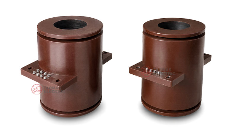
Product Display


The LMZB3-10Q / 137 has a cylindrical cast-resin body with a central hollow aperture and a square mounting base. The primary cable or busbar passes through the aperture, while secondary terminals are arranged on the terminal block area of the cast-resin body for connection to meters, relays, and monitoring devices.
Applications
- 10kV, 11kV and 12kV class indoor medium-voltage switchgear
- High-current feeder cabinets, incoming panels, and outgoing panels
- Current measurement and electric energy metering circuits
- Relay protection circuits requiring 5P accuracy class performance
- Cable-through or busbar-through current sensing in indoor distribution systems
- Industrial substations, commercial power rooms, and utility distribution equipment
Features
- Hollow cable/busbar-through structure: The primary cable, copper bar, or busbar passes through the CT aperture, making the product suitable for high-current indoor switchgear circuits.
- Fully enclosed epoxy resin casting: The cast-resin body provides insulation strength, mechanical support, and stable indoor operation.
- High-current range: Catalogue ratios cover 1500A to 5000A, suitable for large feeder and busbar circuits.
- Metering and protection combinations: Accuracy combinations include 0.2/5P, 0.5/5P, and 5P/5P configurations for different secondary circuit duties.
- International project compatibility: The 12/42/75kV insulation level supports common 10kV, 11kV and 12kV class indoor applications after project confirmation.
- Defined creepage distance: The catalogue lists a surface creepage distance of 240mm for insulation coordination reference.
Principle
The LMZB3-10Q / 137 current transformer operates according to electromagnetic induction. When primary current flows through the cable or busbar passing through the central aperture, magnetic flux is generated in the ring core. The secondary winding induces a proportional output current, normally 5A or 1A, for measuring instruments, energy meters, protection relays, or monitoring devices.
Because the primary conductor is not wound around the core, the product is suitable for high-current circuits where a cable or busbar can pass directly through the CT aperture. For measurement circuits, accuracy class and rated output must match the connected burden. For protection circuits, 5P class selection should be coordinated with relay settings and expected fault-current conditions.
Model Designation
The model code LMZB3-10Q / 137 can be interpreted as follows:
| Code | Meaning |
|---|---|
| L | Current transformer |
| M | Bus type / cable-busbar through-window structure |
| Z | Epoxy resin casting insulation |
| B | Protection level / protection core configuration |
| 3 | Design sequence code |
| 10 | Rated voltage class: 10kV |
| Q | Reinforced type |
| 137 | Nominal aperture / inner-hole reference code |
Technical Data
| Item | Specification |
|---|---|
| Rated voltage class | 10kV class; suitable for 10kV, 11kV and 12kV class indoor applications by project confirmation |
| Rated insulation level | 12/42/75kV |
| Rated frequency | 50Hz or 60Hz |
| Ambient temperature | -5°C to +40°C |
| Rated primary current | 1500A to 5000A |
| Rated secondary current | 5A or 1A |
| Accuracy combinations | 0.2/5P10, 0.5/5P10, 0.2/5P15, 0.5/5P15, 0.2/5P20, 0.5/5P20, 5P10/5P10, 5P15/5P15, 5P20/5P20 |
| Rated secondary output | 30/75, 50/75, 30/50, 50/50, 30/30, 40/80, 60/80, 40/60, 60/60, 40/40, 80/80, 75/75, 50/50, 30/30 according to ratio and accuracy combination |
| Surface creepage distance | 240mm |
| Applicable standards | GB20840.2-2014, IEC61869-2:2003, and customer-specific requirements |
Selection Table
The selection table is organized by current range and shared creepage distance. Long table headers and dense accuracy/output data are wrapped into multiple lines to keep the website layout readable.
| Rated
Primary Current (A) |
Accuracy
Class Combination |
Rated
Secondary Output (VA) |
Surface
Creepage Distance (mm) |
|---|---|---|---|
| 1500-2500 | 0.2 / 5P10 | 30 / 75 | 240 |
| 0.5 / 5P10 | 50 / 75 | ||
| 0.2 / 5P15 | 30 / 50 | ||
| 0.5 / 5P15 | 50 / 50 | ||
| 0.2 / 5P20 | 30 / 30 | ||
| 0.5 / 5P20 | 50 / 30 | ||
| 5P10 / 5P10 | 75 / 75 | ||
| 5P15 / 5P15 | 50 / 50 | ||
| 5P20 / 5P20 | 30 / 30 | ||
| 3000-4000 | 0.2 / 5P10 | 40 / 80 | |
| 0.5 / 5P10 | 60 / 80 | ||
| 0.2 / 5P15 | 40 / 60 | ||
| 0.5 / 5P15 | 60 / 60 | ||
| 0.2 / 5P20 | 40 / 40 | ||
| 0.5 / 5P20 | 60 / 40 | ||
| 3000-4000 | 5P10 / 5P10 | 80 / 80 | |
| 5P15 / 5P15 | 60 / 60 | ||
| 5P20 / 5P20 | 40 / 40 | ||
| 5000 | 0.2 / 5P10 | 40 / 75 | 240 |
| 0.5 / 5P10 | 60 / 75 | ||
| 0.2 / 5P15 | 40 / 50 | ||
| 0.5 / 5P15 | 60 / 50 | ||
| 0.2 / 5P20 | 40 / 30 | ||
| 0.5 / 5P20 | 60 / 30 | ||
| 5P10 / 5P10 | 75 / 75 | ||
| 5P15 / 5P15 | 50 / 50 | ||
| 5P20 / 5P20 | 30 / 30 |
Note: If user requirements exceed the listed range, final parameters may be determined by agreement between manufacturer and purchaser.
Dimensions
| Item | Catalogue Reference |
|---|---|
| Central aperture | Ø137 nominal inner-hole reference |
| Outer body diameter | Ø268 reference from outline drawing |
| Overall length | 350±2mm reference |
| Mounting plate height | 345mm reference |
| Hole dimension | Opening drawing shows Ø275 reference and 4-Ø14 mounting holes |
| Weight | Reference value depends on final configuration |
Service Conditions
- Installation location: indoor medium-voltage switchgear
- Rated voltage: 10kV, 11kV and 12kV class systems by project confirmation
- Rated frequency: 50Hz or 60Hz
- Ambient temperature: -5°C to +40°C
- The installation environment should be free from severe vibration, corrosive gas, explosive medium, conductive dust, heavy pollution and abnormal condensation.
- For high altitude, coastal, humid or heavy-pollution service conditions, technical confirmation is recommended before ordering.
Standards and Compliance
The LMZB3-10Q / 137 current transformer is designed according to GB20840.2-2014, IEC61869-2:2003, and customer-specific requirements shown in the catalogue. Project documentation may also specify additional routine tests, type test references, insulation coordination, partial discharge requirements, or special marking requirements.
Installation and Dimensions

This product is installed through a switchgear wall or panel with the cable or busbar passing through the central aperture. The mounting plate, aperture size, base dimensions, terminal position and creepage distance must be confirmed before switchgear manufacturing. For high-current applications, busbar clearance and phase-to-ground insulation distance should be checked carefully.
Safety Notes
- Confirm current ratio, secondary current, accuracy combination, rated output and aperture size before production.
- Check cable or busbar size against the Ø137 aperture and approved outline drawing.
- Verify mounting hole positions, installation clearance, creepage distance and terminal accessibility.
- The CT secondary circuit must not be open-circuited while primary current is flowing.
- Before disconnecting meters or relays, short-circuit the secondary circuit with an approved shorting device.
- One point of the secondary circuit should be grounded according to the project electrical safety practice.
- Installation and commissioning shall be performed by qualified medium-voltage electrical personnel.
Ordering Info
- Product model: LMZB3-10Q / 137
- Rated primary current and rated secondary current
- Accuracy class combination and rated output for each secondary core
- Required protection class: 5P10, 5P15 or 5P20
- Cable or busbar size and aperture requirement
- Mounting drawing, terminal direction and switchgear layout
- Applicable standard, routine test report and certificate requirements
- Quantity, label language, packaging and project documentation requirements
Selection Guide
- Confirm voltage class: Use this product for indoor 10kV, 11kV and 12kV class switchgear after insulation coordination is confirmed.
- Select current ratio: Choose the rated primary current according to feeder current, busbar capacity and protection setting.
- Check aperture size: Confirm that the cable, copper bar or busbar can pass through the Ø137 aperture safely.
- Define core functions: Use 0.2 or 0.5 for metering and 5P10/5P15/5P20 for protection.
- Verify rated output: Ensure connected meter, relay and cable burdens do not exceed the rated secondary output.
- Confirm creepage distance: Check the 240mm creepage distance against project insulation requirements.
- Approve drawings: Confirm mounting holes, aperture, terminal direction and base plate dimensions before cabinet production.