Product Overview
The LMZB6-10Q(L)/150 current transformer is an indoor, fully enclosed, epoxy cast-resin, cable/busbar-through current transformer for medium-voltage switchgear. It is designed for current measurement, electric energy metering, feeder monitoring, and relay protection in AC power systems with rated frequency of 50Hz or 60Hz. For international project documentation, this model can be described for 10kV, 11kV and 12kV class indoor switchgear applications, subject to final insulation coordination and project requirements.
This model should be treated as LMZB6-10Q(L)/150, not simply LMZB6-10Q / L50. The “Q(L)” indicates a reinforced / dimensional variant within the LMZB6-10Q product family, while “150” is the key aperture or structure reference used for cable or busbar-through installation. Compared with the LMZB6-10Q / 160 type, the LMZB6-10Q(L)/150 should be positioned as a different mechanical and installation variant, especially when cabinet layout, total height, aperture clearance, and terminal box direction are important.
The product uses a hollow through-window structure. The primary cable, copper bar, or busbar passes through the central aperture, while the magnetic core and secondary windings are fully encapsulated in epoxy resin. The external secondary terminal box supports convenient wiring and maintenance in fixed indoor switchgear, feeder cabinets, and high-current distribution panels.
Product Type
| Item | Specification |
|---|---|
| Product name | Indoor Fully Enclosed Epoxy Cast-Resin Cable/Busbar-Through Current Transformer |
| Model | LMZB6-10Q(L)/150 |
| Structure | Fully enclosed epoxy cast-resin body with 150-type hollow cable/busbar-through aperture |
| Voltage class | 10kV, 11kV and 12kV class indoor medium-voltage systems |
| Rated insulation level | 12/42/75kV |
| Rated frequency | 50Hz / 60Hz |
| Rated secondary current | 5A or 1A |
| Rated primary current | 1500A, 2000A, 3000A, 4000A, 5000A |
| Installation feature | Q(L)/150 dimensional variant for indoor cabinet installation |
| Typical application | Current measurement, energy metering, relay protection, feeder monitoring |
Product Display
/150 Cast-Resin Cable/Busbar-Through Current Transformer Thomas Electric")
/150 Cast-Resin Cable/Busbar-Through Current Transformer Thomas Electric")
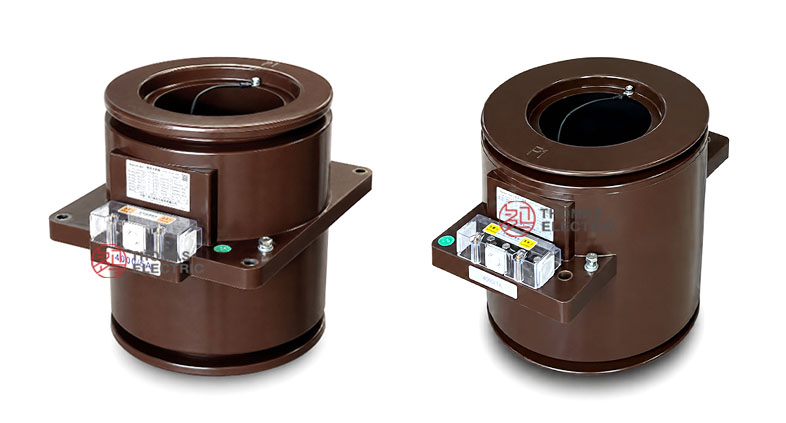
The LMZB6-10Q(L)/150 has a cylindrical resin body, a square mounting base, a 150-type conductor passage, and an external secondary terminal box. The design is suitable for switchgear where the primary conductor passes through the transformer body and the secondary terminals must remain accessible for wiring, inspection, and maintenance.
Applications
- 10kV, 11kV and 12kV class indoor medium-voltage switchgear
- Fixed metal-enclosed switchgear and high-current feeder cabinets
- Incoming and outgoing panels requiring cable or busbar-through CT installation
- Current measurement and electric energy metering circuits
- Relay protection circuits using 5P10, 5P15, 5P20, 5P25, or 5P30 protection cores
- OEM cabinet projects where CT height, aperture clearance, terminal box direction, and mounting position must be confirmed before production
Features
- Correct model designation: The proper model is LMZB6-10Q(L)/150, identifying a Q(L) reinforced / dimensional variant with a 150-type aperture reference.
- Fully enclosed cast-resin body: Epoxy resin encapsulation protects the magnetic core and secondary windings, improving insulation stability and mechanical strength.
- Cable/busbar-through structure: The primary cable, copper bar, or busbar passes through the hollow aperture, making the CT suitable for high-current circuits without a wound primary conductor.
- 5A and 1A secondary options: 5A suits traditional metering and relay circuits, while 1A helps reduce secondary burden for longer wiring or modern digital devices.
- Metering and protection combinations: The product supports 0.2S / 0.5 metering cores and 5P protection cores in multiple combined configurations.
- Terminal box design: The external secondary terminal box supports clearer wiring separation, easier inspection, and safer maintenance access inside the cabinet.
Principle
The LMZB6-10Q(L)/150 current transformer operates according to electromagnetic induction. The primary conductor passes through the aperture and carries the primary current. This current produces magnetic flux in the magnetic core, and the secondary winding induces a proportional current signal for measuring instruments, energy meters, protection relays, or monitoring equipment.
Because the product is a cable/busbar-through structure, there is no wound primary coil inside the CT. This reduces the complexity of high-current primary connection and makes the product suitable for large feeder circuits. For accurate operation, the selected secondary current, accuracy class, rated output, and connected burden must be coordinated with the metering device or relay protection scheme.
Model Designation
/150 Cast-Resin Cable/Busbar-Through Current Transformer Thomas Electric")
| Code | Meaning |
|---|---|
| L | Current transformer |
| M | Busbar / cable-through structure |
| Z | Epoxy resin casting insulation |
| B | Protection-class configuration available |
| 6 | Design sequence code |
| 10 | Rated voltage class: 10kV |
| Q(L) | Reinforced / dimensional variant reference |
| 150 | Aperture or structural size reference for cable/busbar-through installation |
Technical Data
| Item | Specification |
|---|---|
| Rated voltage class | 10kV class; suitable for 10kV, 11kV and 12kV class indoor systems by project confirmation |
| Rated insulation level | 12/42/75kV |
| Rated frequency | 50Hz / 60Hz |
| Rated secondary current | 5A or 1A |
| Rated primary current | 1500A to 5000A |
| Accuracy class | 0.2S, 0.5, 5P10, 5P15, 5P20, 5P25, 5P30 |
| Rated output | 10VA to 60VA depending on ratio, secondary current, accuracy class, and core combination |
| Load power factor | cosφ = 0.8 lagging for catalogue output reference |
| Ambient temperature | -25°C to +40°C |
| Applicable standards | GB20840.1-2010, GB20840.2-2014, IEC61869-2:2012, and customer-specific requirements |
Selection Table
The following table summarizes the main catalogue selection logic. Long table cells are split into multiple lines for responsive display.
| Rated
Current Ratio (A) |
Accuracy Class
Combination |
Rated
Output |
Secondary
Current |
Dimension
Reference |
|---|---|---|---|---|
| 1500/5 | 0.2S / 0.5 / 5P15 / 5P15 0.2S / 0.5 / 5P20 / 5P20 0.2S / 0.5 / 5P25 / 5P25 |
15/20/40/40 15/20/30/30 15/20/15/15 |
5A | Q(L)/150 variant |
| 2000/5 | 0.2S / 0.5 / 5P15 / 5P15 0.2S / 0.5 / 5P20 / 5P20 0.2S / 0.5 / 5P25 / 5P25 |
15/20/50/50 15/20/30/30 15/20/20/20 |
||
| 3000/5 | 0.2S / 0.5 / 5P15 / 5P15 0.2S / 0.5 / 5P20 / 5P20 0.2S / 0.5 / 5P25 / 5P25 |
20/30/50/50 20/30/30/30 20/30/20/20 |
||
| 4000/5 | 0.2S / 0.5 / 5P15 / 5P15 0.2S / 0.5 / 5P20 / 5P20 0.2S / 0.5 / 5P25 / 5P25 |
30/40/50/50 30/40/30/30 30/40/20/20 |
||
| 5000/5 | 0.2S / 0.5 / 5P15 / 5P15 0.2S / 0.5 / 5P20 / 5P20 0.2S / 0.5 / 5P25 / 5P25 |
30/40/60/60 30/40/30/30 30/40/20/20 |
||
| 1500/1 | 0.2S / 0.5 / 5P10 / 5P10 0.2S / 0.5 / 5P15 / 5P15 0.2S / 0.5 / 5P20 / 5P20 |
10/15/40/40 10/15/25/25 10/15/15/15 |
1A | Q(L)/150 variant |
| 2000/1 | 0.2S / 0.5 / 5P10 / 5P10 0.2S / 0.5 / 5P15 / 5P15 0.2S / 0.5 / 5P20 / 5P20 |
10/15/50/50 10/15/30/30 10/15/20/20 |
||
| 3000/1 | 0.2S / 0.5 / 5P10 / 5P10 0.2S / 0.5 / 5P15 / 5P15 0.2S / 0.5 / 5P20 / 5P20 |
10/15/50/50 10/15/30/30 10/15/15/15 |
||
| 4000/1 | 0.2S / 0.5 / 5P10 / 5P10 0.2S / 0.5 / 5P15 / 5P15 |
15/20/50/50 15/20/30/30 |
||
| 5000/1 | 0.2S / 0.5 / 5P20 / 5P20 | 10/10/15/15 |
Note: If project requirements exceed the listed range, final parameters may be determined by technical agreement between manufacturer and purchaser.
Dimensions
| Item | Catalogue Reference |
|---|---|
| Aperture reference | 150-type hollow opening for cable or busbar-through installation |
| Overall height | 310mm or 360mm reference according to variant data |
| Mounting width | 294mm reference |
| Opening plate reference | 260mm / 315mm reference shown in hole dimension drawing |
| Terminal box | External secondary terminal box mounted on the cast-resin body |
| Mounting holes | Four mounting holes shown in the outline drawing |
Terminals
The incoming side of the primary conductor is marked as P1. The first secondary winding is marked as 1S1 / 1S2, and the second secondary winding can be marked as 2S1 / 2S2 where a protection or additional secondary circuit is supplied. Terminal configuration must be confirmed according to the ordered accuracy class combination and approved wiring diagram.
| Terminal | Function | Application Note |
|---|---|---|
| P1 | Primary incoming side | Identifies primary current direction and polarity reference. |
| 1S1 / 1S2 | First secondary winding | Usually used for metering or first specified secondary core. |
| 2S1 / 2S2 | Second secondary winding | Usually used for protection or additional secondary output. |
| Grounding point | Protective grounding | Grounding shall follow the project wiring and safety requirements. |
Service Conditions
- Installation location: indoor medium-voltage switchgear
- Rated voltage: 10kV, 11kV and 12kV class systems by project confirmation
- Rated frequency: 50Hz / 60Hz
- Ambient temperature: -25°C to +40°C
- The installation environment should be free from severe vibration, corrosive gas, explosive medium, conductive dust, heavy pollution, and abnormal condensation.
- For high altitude, coastal, humid or heavy-pollution service conditions, technical confirmation is recommended before ordering.
Standards and Compliance
The LMZB6-10Q(L)/150 current transformer is designed according to GB20840.1-2010, GB20840.2-2014, IEC61869-2:2012, and customer-specific requirements. Routine project documentation may include ratio test, polarity verification, accuracy test, insulation test, and power-frequency withstand test according to the agreed standard.
Installation and Dimensions
/150 Cast-Resin Cable/Busbar-Through Current Transformer Thomas Electric")
This product is suitable for indoor metal-enclosed switchgear where the cable or busbar passes through the current transformer aperture. Before cabinet production, the aperture clearance, conductor size, mounting holes, terminal box direction, total height, phase-to-ground distance, and secondary wiring access should be confirmed with the approved outline drawing.
Safety Notes
- Confirm primary current, secondary current, accuracy class combination, rated output, and installation dimensions before production.
- Check that the cable, copper bar, or busbar can pass through the 150-type aperture with sufficient insulation clearance.
- Check terminal box direction and maintenance access before switchgear assembly.
- The CT secondary circuit must not be open-circuited while primary current is flowing.
- Before disconnecting meters or relays, short-circuit the secondary circuit using an approved shorting device.
- One point of the secondary circuit should be grounded according to project electrical safety practice.
- Installation and commissioning shall be performed by qualified medium-voltage electrical personnel.
Ordering Info
- Product model: LMZB6-10Q(L)/150
- Rated primary current and rated secondary current: 5A or 1A
- Accuracy class combination and rated output for each secondary core
- Required protection class: 5P10, 5P15, 5P20, 5P25, 5P30, or project-specific requirement
- Cable or busbar size and aperture requirement
- Total height and installation dimension requirement
- Mounting drawing, terminal direction, and switchgear layout
- Applicable standard, routine test report, and certificate requirements
- Quantity, label language, packaging, and project documentation requirements
Selection Guide
- Confirm voltage class: Use this product for indoor 10kV, 11kV and 12kV class switchgear after insulation coordination is confirmed.
- Select current ratio: Choose 1500A to 5000A according to feeder current, busbar capacity, and protection setting.
- Select secondary current: Use 5A for conventional systems or 1A where lower burden or longer secondary wiring is required.
- Confirm mechanical fit: Check whether the LMZB6-10Q(L)/150 dimensions fit the cabinet design.
- Define core functions: Use 0.2S / 0.5 for metering and 5P protection classes according to relay requirements.
- Verify rated output: Ensure the connected meter, relay, and wiring burden do not exceed the selected rated output.
- Approve drawings: Confirm aperture, mounting holes, terminal box position, and conductor path before production.