Product Overview
The LXK-φ80/φ100/φ120/φ150/φ180/φ200/φ240/φ260 split-core zero sequence current transformer is an indoor epoxy cast-resin core-balance current transformer designed for cable earth fault protection, residual current detection, and grounding fault monitoring. The series is used in indoor AC distribution systems with rated frequency of 50Hz or 60Hz, and is suitable for small-current grounding systems and cable feeder protection applications up to 35kV when matched with the correct cable insulation and protection scheme.
This LXK series is the open-type / split-core version. The transformer body can be opened, installed around an existing cable group, and then closed and fastened by a clamping band. Compared with an integrated non-split zero sequence CT, the split-core LXK design is more suitable for retrofit projects, installed switchgear, cable outlet compartments, and maintenance replacement where the cable cannot be disconnected or passed through a closed ring.
Product Type
| Item | Specification |
|---|---|
| Product name | LXK-φ80/φ100/φ120/φ150/φ180/φ200/φ240/φ260 Split-Core Zero Sequence Current Transformer |
| Model series | LXK-80, LXK-100, LXK-120, LXK-150, LXK-180, LXK-200, LXK-240, LXK-260 |
| Product structure | Indoor epoxy cast-resin split-core / open-type zero sequence current transformer |
| Inner diameter options | φ80, φ100, φ120, φ150, φ180, φ200, φ240, φ260 |
| Rated insulation level | 0.72/3kV |
| Rated frequency | 50Hz / 60Hz |
| Rated secondary current | 5A or 1A |
| Protection class | 10P5, 10P10, 10P15, 10P20 according to selected model and ratio |
| Installation location | Indoor |
| Typical applications | Cable earth fault protection, zero sequence current detection, residual current monitoring, relay protection input |
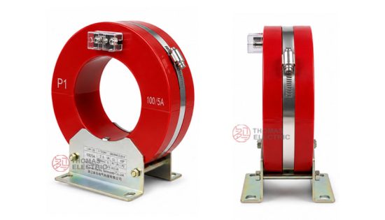
Product Display


Main Applications
- Indoor cable earth fault protection for small-current grounding systems
- Zero sequence current detection in three-phase cable feeder circuits
- Residual current monitoring in switchgear, ring network cabinets, and protection panels
- Grounding fault alarm and trip protection circuits
- Retrofit installation around existing cables without removing the cable head
- Motor feeder, generator feeder, cable branch, and distribution line protection
- Relay protection systems requiring 5A or 1A secondary current input
Key Technical Features
- Split-core open structure: The transformer can be opened and installed around existing cables, reducing installation work and avoiding cable disconnection.
- Inner diameter clearly defined: Apertures from φ80 to φ260 cover different cable group sizes; the model title should include the selected inner diameter.
- Epoxy cast-resin insulation: The core and winding are cast with epoxy resin for insulation performance, moisture resistance, and mechanical stability.
- Zero sequence detection: Detects residual current generated by insulation faults or single-phase grounding faults.
- Protection relay output: Provides 5A or 1A secondary current signals for relay protection, monitoring, and alarm systems.
- 10P protection classes: 10P5 to 10P20 options are available according to model size, current ratio, and rated burden.
Working Principle
The LXK split-core zero sequence current transformer measures the vector sum of all phase currents passing through its aperture. Under normal balanced operating conditions, the sum of the three-phase currents is close to zero. When a ground fault, insulation fault, or leakage condition occurs, the balance is broken and zero sequence current appears. The CT converts the residual current into a secondary signal for the connected relay or monitoring device.
For correct protection, all protected phase conductors must pass through the same aperture in the same direction. Cable screen, armor, neutral, and PE conductor routing should follow the protection scheme. Incorrect routing can cancel or distort the residual current signal.
Model Designation

The LXK model code can be interpreted as follows:
| Code | Meaning |
|---|---|
| L | Current transformer |
| X | Zero sequence / residual current detection |
| K | Open-type / split-core structure in this product series |
| 80 / 100 / 120 / 150 / 180 / 200 / 240 / 260 | Nominal aperture diameter in millimeters |
| Dimension group, such as 120/204×57 | Inner diameter / outer diameter × body thickness reference |
Structure Introduction
The LXK open-type zero sequence current transformer is composed of two cast-resin semi-ring sections. During installation, the stainless steel fastening band or clamping mechanism is released, the two sections are placed around the cable group, and the core is closed into a complete magnetic path. After closing, the clamping band should be tightened evenly to ensure full contact between the core mating surfaces.
This split-core structure is especially useful for existing cable systems. It allows zero sequence protection to be added or replaced without cutting the cable, removing the cable head, or changing the primary conductor route. The cast-resin body protects the secondary winding and magnetic core, while the cable itself provides the main primary insulation.
Technical Data
| Item | Specification |
|---|---|
| Model series | LXK-80 to LXK-260 split-core type |
| Product type | Indoor epoxy cast-resin split-core zero sequence current transformer |
| Applicable system | Indoor small-current grounding systems and cable feeder protection systems up to 35kV |
| Rated insulation level | 0.72/3kV |
| Rated frequency | 50Hz / 60Hz |
| Rated secondary current | 5A or 1A |
| Protection class | 10P5, 10P10, 10P15, 10P20 according to selected model |
| Rated output | 1VA to 15VA depending on aperture size, current ratio, and protection class |
| Ambient temperature | -25°C to +40°C |
| Secondary winding withstand voltage | 3kV power-frequency withstand voltage, subject to technical agreement |
| Applicable standards | GB/T 20840.1-2010, GB/T 20840.2-2014; IEC 61869-1 and IEC 61869-2 reference framework |
Series Aperture and Model Reference
| Model | Inner
Diameter |
Typical
Dimension Code |
Protection Class
Range |
Typical Rated
Output Range |
Selection
Use |
|---|---|---|---|---|---|
| LXK-80 | φ80 mm | 80/165×57 | 10P5 to 10P10 | 5VA to 2.5VA | Compact cable group and small cabinet space |
| LXK-100 | φ100 mm | 100/180×55, 100/180×57 | 10P5 to 10P10 or 10P15 | 5VA to 2.5VA or 10VA to 2.5VA | Standard cable feeder protection |
| LXK-120 | φ120 mm | 120/204×57, 120/210×65, 120/210×100, 120/250×80 | 10P5 to 10P20 | 1VA to 15VA | Common ring network cabinet and cable outlet application |
| LXK-150 | φ150 mm | 150/235×57, 150/280×80 | 10P5 to 10P20 | 10VA to 2.5VA or 15VA to 5VA | Medium cable group protection |
| LXK-180 | φ180 mm | 180/265×57, 180/310×80 | 10P5 to 10P20 | 10VA to 2.5VA or 15VA to 5VA | Large cable feeder protection |
| LXK-200 | φ200 mm | 200/330×80 | 10P5 to 10P20 | 15VA to 2.5VA | High-capacity cable group |
| LXK-240 | φ240 mm | 240/350×80 | 10P5 to 10P20 | 15VA to 5VA | Large-diameter cable group |
| LXK-260 | φ260 mm | 260/370×80 | 10P5 to 10P20 | 15VA to 1.5VA or as specified | Maximum aperture option in this series |
Rated Current Ratio and Output Reference
| Current
Ratio |
Secondary
Current |
Typical Rated
Output Range |
Applicable
Protection Class |
|---|---|---|---|
| 50/5 | 5A | 5VA to 1VA depending on model | 10P5 to 10P20 |
| 75/5 | 5A | 10VA to 1VA depending on model | 10P5 to 10P20 |
| 100/5 | 5A | 10VA to 2.5VA depending on model | 10P5 to 10P20 |
| 150/5 | 5A | 10VA to 5VA depending on model | 10P5 to 10P20 |
| 200/5 | 5A | 15VA to 5VA depending on model | 10P5 to 10P20 |
| 250/5 | 5A | 15VA to 5VA depending on model | 10P5 to 10P20 |
| 300/5 | 5A | 15VA to 2.5VA depending on model | 10P5 to 10P20 |
| 400/5 | 5A | 10VA to 2.5VA depending on model | 10P5 to 10P20 |
| 50/1 to 250/1 | 1A | 5VA to 1VA depending on model | 10P5 to 10P20 |
Note: The exact rated output depends on aperture size, core width, current ratio, secondary current and protection class. Parameters outside the catalogue range can be confirmed by technical agreement.
Service Conditions
- Installation location: indoor
- Rated frequency: 50Hz / 60Hz
- Applicable system: small-current grounding systems and cable feeder protection systems up to 35kV
- Ambient temperature: -25°C to +40°C
- Recommended environment: no severe vibration, corrosive gas, conductive dust, explosive medium, heavy moisture or serious pollution
- All protected phase conductors should pass through the same CT aperture in the same direction
- The split-core contact surface should be clean and fully closed before operation
- For special cable diameter, relay model, wiring distance, burden or sensitivity requirement, confirm parameters before ordering
Standards and Compliance
The LXK split-core zero sequence current transformer series is designed according to GB/T 20840.1-2010 and GB/T 20840.2-2014, with reference to the IEC 61869 instrument transformer framework. Routine test items, marking, insulation tests, ratio verification and protection accuracy verification can be supplied according to project requirements.
Installation and Dimensions

Model Size and Dimension Reference
| Model | Type /
Dimension Code |
φd | φD | C | a | b | A | B | E | L | f | h |
|---|---|---|---|---|---|---|---|---|---|---|---|---|
| LXK-80 | 80/165×57 | 80 | 165 | 57 | 110 | 60 | 130 | 120 | 102 | 185 | 10 | 17 |
| LXK-100 | 100/180×55 | 100 | 177 | 55 | 110 | 90 | 130 | 118 | 114 | 203 | 10 | 17 |
| LXK-100 | 100/180×57 | 100 | 180 | 57 | 110 | 90 | 130 | 120 | 113 | 203 | 10 | 17 |
| LXK-120 | 120/204×57 | 120 | 204 | 57 | 110 | 90 | 130 | 120 | 121 | 223 | 10 | 17 |
| LXK-120 | 120/210×65 | 120 | 210 | 65 | 110 | 100 | 130 | 125 | 123 | 228 | 10 | 17 |
| LXK-120 | 120/210×100 | 120 | 210 | 100 | 110 | 133 | 130 | 163 | 123 | 228 | 13 | 23 |
| LXK-120 | 120/250×80 | 120 | 250 | 80 | 150 | 140 | 190 | 174 | 153 | 268 | 10 | 17 |
| LXK-150 | 150/235×57 | 150 | 235 | 57 | 150 | 125 | 190 | 151 | 150 | 267 | 13 | 23 |
| LXK-150 | 150/280×80 | 150 | 280 | 80 | 150 | 140 | 190 | 174 | 158 | 297 | 13 | 23 |
| LXK-160 | 160/250×80 | 160 | 250 | 80 | 150 | 140 | 190 | 174 | 156 | 290 | 13 | 23 |
| LXK-180 | 180/265×57 | 180 | 265 | 57 | 150 | 125 | 190 | 161 | 165 | 298 | 13 | 23 |
| LXK-180 | 180/310×80 | 180 | 310 | 80 | 220 | 125 | 260 | 164 | 190 | 365 | 13 | 23 |
| LXK-200 | 200/330×80 | 200 | 330 | 80 | 220 | 125 | 260 | 164 | 200 | 365 | 13 | 23 |
| LXK-240 | 240/350×80 | 240 | 350 | 80 | 220 | 125 | 260 | 164 | 220 | 395 | 13 | 23 |
| LXK-260 | 260/370×80 | 260 | 370 | 80 | 220 | 125 | 260 | 164 | 229 | 410 | 13 | 23 |
Unit: mm. Final dimensions, fastening band layout, terminal box position and installation clearance are subject to the approved outline drawing.
Before installation, confirm that the selected aperture can fully cover the cable group and that the cable bending radius is compatible with the cabinet layout. Open the split-core body by releasing the fastening band, place the transformer around the cable group, close the core, and tighten the band evenly. Any gap, dust, metal particles or misalignment at the mating surface may affect sensitivity and output stability.
Connection and Wiring Notes
- All phase conductors should pass through the same aperture in the same direction.
- Do not pass only one phase conductor through the CT when it is used for zero sequence protection.
- Connect secondary terminals K1/K2 or S1/S2 according to the relay wiring diagram and terminal marking.
- Observe polarity when the relay protection scheme requires directional or coordinated operation.
- One point of the secondary circuit should be grounded according to applicable protection practice.
- The secondary circuit of a current transformer must not be open-circuited when the primary circuit is energized.
- Check relay burden, secondary cable length and terminal connection before commissioning.
Installation and Safety Notes
- Confirm the model, aperture diameter, current ratio, secondary current, protection class and rated output before installation.
- Check that all protected cables, including routing requirements for shield or armor conductors, match the protection scheme.
- Keep the core mating surface clean and ensure full contact before tightening the fastening band.
- Do not energize the system if the split-core body is not fully closed or the fastening band is loose.
- Install the transformer in an indoor cabinet or cable compartment according to the approved drawing.
- Installation, testing and maintenance should be performed by qualified electrical personnel.
Selection Guidelines
- Confirm inner diameter: Select φ80, φ100, φ120, φ150, φ180, φ200, φ240 or φ260 according to the outside dimension of the complete cable group.
- Confirm split-core requirement: Use the open-type LXK when the cable is already installed or cannot be disconnected.
- Confirm body thickness: Choose 55, 57, 65, 80 or 100 mm structure according to rated output requirement and cabinet depth.
- Confirm current ratio: Select the ratio according to relay input, setting range and fault detection requirement.
- Select secondary current: Choose 5A or 1A according to the relay or monitoring device input.
- Choose protection class: Select 10P5 to 10P20 according to the required protection accuracy and burden.
- Check wiring burden: The relay input, secondary cable and terminal burden must not exceed the rated output.
- Verify conductor routing: Confirm whether cable shield, armor, neutral or PE conductor should pass through or bypass the CT according to the protection scheme.