Product Overview
The LZJC-10 / LZJC(D)-10 / LZJC-12 / LZJC(D)-12 current transformer is an indoor support-type epoxy cast-resin insulated current transformer designed for medium-voltage AC power systems. It is suitable for 10kV, 11kV, and 12kV switchgear applications and is used for current measurement, electric energy metering, feeder monitoring, relay protection, and differential protection in systems with rated frequency of 50Hz or 60Hz.
The product adopts a support-type cast-resin structure. The primary and secondary windings are molded with epoxy resin, and the magnetic cores are fixed on the cast body by a clamp structure. The cast body provides insulation support, mechanical strength, moisture resistance, and stable electrical performance for indoor metal-clad switchgear and circuit breaker cabinet applications.
Product Type
| Item | Specification |
|---|---|
| Product name | Indoor Epoxy Cast-Resin Current Transformer |
| Model series | LZJC-10 / LZJC(D)-10 / LZJC-12 / LZJC(D)-12 |
| Product structure | Indoor support-type, epoxy cast-resin insulated current transformer |
| Voltage class | 10kV, 11kV, and 12kV medium-voltage systems |
| Rated insulation level | 12/42/75kV reference insulation level for IEC 12kV-class systems |
| Rated frequency | 50Hz / 60Hz |
| Rated secondary current | 5A or 1A according to project requirement |
| Application type | Current measurement, energy metering, relay protection, and differential protection |
| Installation location | Indoor medium-voltage switchgear and metal-clad cabinet systems |
| Applicable standard | IEC 60044-1; IEC 61869-1 / IEC 61869-2 available according to project requirement |
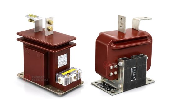
Product Display
-10, LZJC-12 indoor epoxy cast-resin Current Transformer Thomas Electric")
Main Applications
- 10kV, 11kV, and 12kV indoor medium-voltage distribution systems
- Metal-clad switchgear with circuit breaker truck applications
- Current measurement and electric energy metering circuits
- Relay protection and differential protection circuits
- Medium-voltage feeder cabinets, transformer panels, motor control feeders, and distribution rooms
- SCADA, power monitoring, and energy management systems requiring isolated secondary current signals
Key Technical Features
- IEC-oriented voltage class: Suitable for 10kV, 11kV, and 12kV systems, with 12/42/75kV insulation level used as a common IEC 12kV-class reference.
- Epoxy cast-resin insulation: The winding system is molded with epoxy resin to provide insulation strength, mechanical stability, and indoor moisture resistance.
- Support-type construction: The cast body provides mechanical support and insulation for the primary and secondary winding system.
- Differential protection option: The LZJC(D) version is configured for applications where differential protection is required by the switchgear or protection scheme.
- Switchgear-oriented design: The structure is suitable for metal-clad switchgear with breaker truck installation and compact cabinet layouts.
- Flexible secondary configuration: 5A or 1A secondary current, metering/protection classes, and rated output can be specified according to project requirements.
Working Principle
The LZJC series current transformer operates according to electromagnetic induction. When current flows through the primary circuit, magnetic flux is generated in the core, and the secondary winding outputs a proportional current signal to meters, relays, or monitoring devices. The epoxy resin insulation system separates the medium-voltage primary circuit from the low-voltage secondary circuit and supports safe signal transmission under rated service conditions.
For metering applications, the CT should maintain ratio accuracy and phase displacement within the specified burden. For protection applications, the protection winding should provide a reliable current signal during fault-current conditions and coordinate with relay settings, accuracy limit factor, and system short-circuit level.
Model Designation
-10, LZJC-12 indoor epoxy cast-resin Current Transformer Thomas Electric")
| Code | Meaning |
|---|---|
| L | Current transformer |
| Z | Support type |
| J | For metal-clad switchgear with breaker truck |
| C | Support-type cast-resin current transformer structure |
| C(D) | Differential protection version |
| 10 / 12 | Voltage class for 10kV, 11kV, or 12kV medium-voltage applications |
Example: LZJC(D)-10 indicates an indoor support-type cast-resin current transformer for metal-clad switchgear with breaker truck application, configured with a differential protection function and a 10kV-class voltage designation. For 11kV or 12kV projects, the applicable insulation level, nameplate data, and project specification shall be confirmed before ordering.
Technical Data
| Item | Specification |
|---|---|
| Rated voltage class | 10kV / 11kV / 12kV medium-voltage systems |
| Highest voltage for equipment | 12kV class |
| Rated insulation level | 12/42/75kV reference |
| Rated frequency | 50Hz / 60Hz |
| Rated primary current | 5A to 1000A reference range; customized ratios available according to project requirement |
| Rated secondary current | 5A or 1A |
| Accuracy class combination | 0.2 / 10P, 0.2S / 10P, 0.5 / 10P, and project-specific measuring / protection combinations |
| Rated output | 10VA / 15VA or project-specific burden according to secondary core configuration |
| Protection accuracy limit factor | 10 or 15 according to protection core specification |
| Insulation structure | Indoor epoxy cast-resin insulation |
| Installation method | Support-type mounting with bottom installation holes according to approved drawing |
| Applicable standard | IEC 60044-1; IEC 61869-1 / IEC 61869-2 available according to project requirement |
Windings and Terminal Marking
The LZJC / LZJC(D) current transformer can be supplied with measuring, metering, protection, or differential protection secondary configurations. The primary and secondary terminal arrangement shall be confirmed according to the selected model, secondary core quantity, and approved wiring diagram.
| Terminal Marking | Function | Application Note |
|---|---|---|
| P1 / P2 | Primary terminals | The reference primary current direction is normally defined from P1 to P2. |
| 1S1 / 1S2 | First secondary winding | Usually used for metering, measurement, or the first specified secondary core. |
| 2S1 / 2S2 | Second secondary winding | Usually used for relay protection, differential protection, or an additional secondary circuit when required. |
| Earthing bolt | Grounding point | Grounding shall follow the project wiring diagram and local electrical safety requirements. |
Terminal markings follow standard CT polarity conventions. Correct terminal identification shall be observed to ensure metering accuracy, relay direction judgment, and protection performance. The secondary circuit must not be open-circuited when the primary circuit is energized.
Data Reference
| Type | Rated
Voltage (kV) |
Rated
Primary Current (A) |
Rated
Secondary Current (A) |
Accuracy
Class Combination |
Rated
Output (VA) |
Accuracy
Limit Factor |
Short-Time
Thermal Current |
Rated
Dynamic Current |
Weight
Reference |
|---|---|---|---|---|---|---|---|---|---|
| LZJC-10 / LZJC-12 | 10 / 11 / 12 | 5–400 | 5 or 1 | 0.2 / 10P 0.2S / 10P 0.5 / 10P |
10 / 15 | 10 | 50 × I1n | 150 × I1n | Approx. 14kg reference |
| LZJC(D)-10 / LZJC(D)-12 | 600–800 | 10 | 50 × I1n | 100–120 × I1n | |||||
| LZJC(D)-10 / LZJC(D)-12 | 1000 | 15 | 45 × I1n | 90 × I1n |
Note: The selection table is for preliminary engineering reference. Standard and customized current ratios can be supplied according to project requirements. Final current ratio, secondary current, rated output, accuracy class, accuracy limit factor, short-time thermal current, dynamic current, insulation level, and test requirements shall be confirmed according to nameplate data, approved drawings, and factory test reports.
Service Conditions
- Installation location: indoor medium-voltage switchgear
- System voltage: 10kV, 11kV, or 12kV class
- Rated frequency: 50Hz / 60Hz
- Altitude: not over 1000m under standard service conditions
- Ambient temperature: -5°C to +40°C
- Relative humidity: less than 85% at 20°C under reference service conditions
- The installation site should be free from severe vibration, corrosive gas, explosive medium, heavy pollution, and abnormal moisture condensation.
- For high altitude, high humidity, coastal, high pollution, or special switchgear conditions, technical confirmation is recommended before ordering.
Standards & Compliance
The LZJC-10 / LZJC(D)-10 / LZJC-12 / LZJC(D)-12 current transformer can be supplied according to IEC 60044-1, and IEC 61869-1 / IEC 61869-2 requirements can be applied when specified by the project. Routine tests, dielectric tests, polarity verification, ratio test, accuracy test, insulation resistance, and partial discharge requirements should be confirmed according to the final technical agreement.
Installation & Dimensions
-10, LZJC-12 indoor epoxy cast-resin Current Transformer Thomas Electric")
The LZJC series is designed for indoor switchgear installation. The cast body includes mounting holes, clamp structure, rating plate position, earthing bolt, and primary terminal arrangement according to the approved drawing. Final outline dimensions, primary terminal layout, secondary terminal direction, and installation clearances shall be confirmed before switchgear design or batch production.
Structure &7 Dimensions
| Item | Selection Note |
|---|---|
| Mechanical structure | Indoor epoxy cast-resin support-type current transformer |
| Application version | LZJC for standard metering / protection; LZJC(D) for differential protection application |
| Switchgear application | Metal-clad switchgear, feeder cabinet, and breaker truck system |
| Primary terminals | P1 / P2 terminal arrangement according to approved drawing |
| Secondary terminals | S1 / S2 or multi-core secondary terminal arrangement according to project configuration |
| Drawing confirmation | Final outline and mounting dimensions shall be confirmed before switchgear production |
Installation & Safety Notes
- Confirm the model, voltage class, current ratio, secondary current, accuracy class, burden, insulation level, and short-circuit withstand requirement before installation.
- Check switchgear mounting space, primary terminal connection, phase clearance, grounding arrangement, and maintenance access against the approved drawing.
- Connect primary and secondary terminals according to the terminal markings and project wiring diagram.
- The secondary circuit of a current transformer must not be left open when the primary circuit is energized.
- During meter or relay maintenance, short-circuit the CT secondary circuit before disconnecting any secondary wiring.
- The earthing bolt and secondary grounding point shall be connected according to project specification and local electrical safety requirements.
- Installation and maintenance shall be performed by qualified medium-voltage electrical personnel.
Ordering Information
Please provide the following information when ordering or requesting a quotation:
- Product model: LZJC-10, LZJC(D)-10, LZJC-12, or LZJC(D)-12
- System voltage: 10kV, 11kV, or 12kV
- Application requirement: measurement, energy metering, relay protection, or differential protection
- Rated primary current / current transformation ratio
- Rated secondary current: 1A or 5A
- Accuracy class combination and rated output for each secondary core
- Accuracy limit factor and short-circuit withstand requirement
- Insulation level and applicable IEC standard
- Switchgear type, installation layout, terminal direction, and required outline drawing
- Quantity, labeling, certificates, routine test reports, and packaging requirements
- Special customized current ratio, secondary winding, or terminal arrangement requirements
Selection Guidelines
- Confirm system voltage: Select the suitable LZJC or LZJC(D) model for 10kV, 11kV, or 12kV medium-voltage switchgear.
- Confirm application type: Select LZJC for standard measurement / protection and LZJC(D) when differential protection is required.
- Confirm current ratio: Select the primary current according to feeder load, continuous operating current, and relay protection range.
- Confirm secondary current: Select 5A or 1A according to connected devices, secondary wiring distance, and burden calculation.
- Define core configuration: Specify metering, measurement, protection, or combined secondary winding configuration according to the project circuit design.
- Check rated burden: Ensure the total secondary burden, including meters, relays, and wiring loss, does not exceed the rated output of each secondary core.
- Verify short-circuit withstand: Short-time thermal current and dynamic current shall meet the switchgear fault-current level.
- Confirm customization: For non-standard current ratios, special accuracy classes, terminal layouts, or installation constraints, confirm drawings and technical agreement before ordering.
FAQs