Product Overview
The LZJC6-10/145 / LZJC-12 current transformer is an indoor, single-phase, epoxy resin cast current transformer designed for 10kV, 11kV, and 12kV medium-voltage power distribution systems. It is used for current measurement, electric energy metering, feeder monitoring, and relay protection in AC systems with rated frequency of 50Hz or 60Hz.
The product adopts epoxy resin casting insulation and a fully enclosed support structure. The primary winding, secondary winding, and annular magnetic core are encapsulated inside the resin body to provide insulation strength, moisture resistance, mechanical stability, and reliable operation in indoor switchgear environments. A grooved external insulation structure helps improve surface creepage performance and external insulation reliability, making the product suitable for compact switchgear layouts and demanding indoor service conditions.
Product Type
| Item | Specification |
|---|---|
| Product name | Indoor Epoxy Resin Cast Current Transformer |
| Model series | LZJC6-10/145 / LZJC-12 |
| Product structure | Indoor single-phase, epoxy resin cast, fully enclosed support structure |
| Voltage class | 10kV, 11kV, and 12kV medium-voltage systems |
| Rated insulation level | 12/42/75kV reference insulation level for 12kV class systems |
| Rated frequency | 50Hz / 60Hz |
| Rated secondary current | 5A or 1A according to project requirement |
| Core configuration | Metering core, protection core, or combined metering/protection configuration |
| Installation location | Indoor medium-voltage switchgear and distribution equipment |
| Typical applications | Current measurement, energy metering, relay protection, feeder monitoring, switchgear instrumentation |
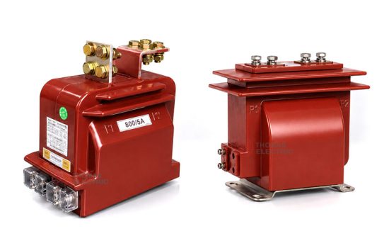
Product Display


Main Applications
- 10kV, 11kV, and 12kV indoor medium-voltage distribution systems
- Air-insulated switchgear, feeder cabinets, circuit breaker panels, and distribution rooms
- Current measurement and electric energy metering circuits
- Relay protection circuits for feeders, transformers, motors, and distribution lines
- Industrial substations, utility distribution systems, and commercial power rooms
- Compact switchgear layouts requiring omni-directional installation and enclosed epoxy insulation
Key Technical Features
- Epoxy resin cast insulation: The primary and secondary windings and annular core are fully encapsulated in epoxy resin, supporting electrical insulation, mechanical strength, and moisture resistance.
- Fully enclosed support construction: The molded body combines current transformation, insulation, and mechanical support functions for indoor medium-voltage switchgear.
- Grooved external insulation: The external groove design helps increase creepage distance and strengthen external insulation performance in humid or polluted indoor environments.
- Omni-directional installation: The compact and lightweight structure supports flexible mounting direction according to cabinet layout and conductor arrangement.
- Metering and protection functions: The product can provide secondary current signals for energy meters, measuring instruments, protection relays, and monitoring devices.
- Standard and customized ratios: In addition to standard current ratios, customized ratios and secondary configurations can be supplied according to project requirements.
Working Principle
The LZJC6-10/145 / LZJC-12 current transformer operates according to electromagnetic induction. The primary current produces magnetic flux in the annular magnetic core, and the secondary winding outputs a proportional current signal to connected measuring instruments, energy meters, protection relays, or monitoring devices. The epoxy resin casting body provides insulation between the medium-voltage primary circuit and the low-voltage secondary circuit.
For metering applications, the transformer should maintain the specified ratio accuracy and phase displacement under the rated burden. For protection applications, the protection winding should provide a reliable secondary signal during fault-current conditions and coordinate with relay settings and short-circuit withstand requirements.
Technical Data
| Item | Specification |
|---|---|
| Rated voltage class | 10kV / 11kV / 12kV medium-voltage systems |
| Highest voltage for equipment | 12kV class |
| Rated insulation level | 12/42/75kV reference |
| Rated frequency | 50Hz / 60Hz |
| Rated primary current | 5A to 1000A reference range; customized ratios available according to project requirement |
| Rated secondary current | 5A or 1A |
| Accuracy class combination | 0.2S / 0.2S, 0.2S / 0.5, 0.2S / 10P, 0.5 / 10P, or project-specific metering/protection combinations |
| Rated output | 10VA / 15VA or customized according to secondary core and burden requirement |
| Metering security factor | FS 5 or FS 10 according to metering core specification |
| Protection accuracy limit factor | ALF 10 or project-specific requirement for protection core |
| Insulation structure | Epoxy resin casting insulation, fully enclosed support construction |
| Installation method | Indoor support installation; mounting direction according to switchgear layout |
| Applicable standard | IEC 60044-1; IEC 61869-1 / IEC 61869-2 available according to project requirement |
Windings and Terminal Marking

The LZJC6-10/145 / LZJC-12 current transformer can be supplied with measuring, metering, protection, or combined secondary winding configurations. The final secondary terminal arrangement shall be confirmed according to the number of secondary cores and the project wiring diagram.
| Terminal Marking | Function | Application Note |
|---|---|---|
| P1 / P2 | Primary terminals | The reference primary current direction is normally defined from P1 to P2. |
| 1S1 / 1S2 | First secondary winding | Usually used for metering, measurement, or the first specified secondary core. |
| 2S1 / 2S2 | Second secondary winding | Usually used for relay protection or an additional secondary circuit when required. |
| Secondary terminal cover | Secondary wiring protection | Terminal layout, cover type, and labeling shall be confirmed by approved drawing. |
Terminal markings follow standard current transformer polarity conventions. Correct terminal identification shall be observed to ensure metering accuracy, relay direction judgment, and protection performance. The secondary circuit must not be open-circuited when the primary circuit is energized.
Rated Current, Accuracy and Short-Circuit Withstand Reference
| Rated Primary Current (A) | Accuracy Class Combination | Rated Output (VA) | FS | ALF | Rated Short-Time Thermal Current | Rated Dynamic Current |
|---|---|---|---|---|---|---|
| 5–200/5 | 0.2S / 0.2S 0.2S / 0.5 0.2S / 10P 0.5 / 10P |
10 / 15 / 15 or project-specific burden | 5 or 10 | 10 or project-specific ALF | 75 × I1n | 180 × I1n |
| 300/5 | 20kA | 50kA | ||||
| 400/5 | 30kA | 75kA | ||||
| 500/5 | 30kA | 75kA | ||||
| 600/5 | 40kA | 80kA | ||||
| 800/5 | 40kA | 80kA | ||||
| 1000/5 | 63kA | 105kA |
Note: The selection table is for preliminary engineering reference. Standard and customized ratios can be supplied according to project requirements. Final current ratio, secondary current, accuracy class, rated output, FS, ALF, short-time thermal current, dynamic current, insulation level, and test requirements shall be confirmed according to the nameplate, approved drawing, and factory test report.
Service Conditions
- Installation location: indoor medium-voltage switchgear
- System voltage: 10kV, 11kV, or 12kV class
- Rated frequency: 50Hz / 60Hz
- Highest voltage for equipment: 12kV
- Ambient temperature: -25°C to +40°C reference range, or according to project requirement
- The installation environment should be free from severe vibration, explosive medium, corrosive gas, heavy conductive dust, and abnormal condensation.
- For high altitude, high humidity, coastal, heavy pollution, high temperature variation, or special cabinet conditions, technical confirmation is recommended before ordering.
Standards and Compliance
The LZJC6-10/145 / LZJC-12 current transformer can be supplied according to IEC 60044-1, and IEC 61869-1 / IEC 61869-2 requirements can be applied when specified by the project. Routine tests, dielectric tests, polarity verification, ratio test, accuracy test, insulation resistance, and partial discharge requirements should be confirmed according to the final technical agreement.
Installation and Dimensions

The LZJC6-10/145 / LZJC-12 series is designed for indoor switchgear installation. Its lightweight epoxy cast body allows flexible mounting orientation, while the grooved external insulation structure supports insulation coordination in compact cabinet layouts. Final outline dimensions, primary terminal layout, mounting holes, secondary terminal direction, and clearance requirements shall be confirmed with the approved drawing before cabinet design or batch production.
Available Structure and Overall Dimensions
| Item | Selection Note |
|---|---|
| Mechanical structure | Indoor epoxy resin cast fully enclosed support structure |
| Installation direction | Omni-directional installation according to switchgear layout and conductor arrangement |
| Primary terminals | P1 / P2 terminal arrangement according to approved drawing |
| Secondary terminals | 1S1 / 1S2 and optional 2S1 / 2S2 according to secondary core configuration |
| External insulation | Grooved resin body for enhanced external insulation performance |
| Drawing confirmation | Final outline and installation dimensions shall be confirmed before switchgear production |
Installation and Safety Notes
- Confirm the model, voltage class, current ratio, secondary current, accuracy class, burden, insulation level, and short-circuit withstand requirement before installation.
- Check switchgear mounting space, conductor connection, phase clearance, grounding arrangement, and maintenance access against the approved drawing.
- Connect primary and secondary terminals according to the terminal markings and project wiring diagram.
- The secondary circuit of a current transformer must not be left open when the primary circuit is energized.
- During meter or relay maintenance, short-circuit the CT secondary circuit before disconnecting any secondary wiring.
- One point of the secondary circuit should be grounded according to project specification and local electrical safety requirements.
- Installation and maintenance shall be performed by qualified medium-voltage electrical personnel.
Ordering Information
Please provide the following information when ordering or requesting a quotation:
- Product model: LZJC6-10/145 or LZJC-12
- System voltage: 10kV, 11kV, or 12kV
- Rated primary current / current transformation ratio
- Rated secondary current: 1A or 5A
- Required metering and protection accuracy class combination
- Rated output / burden for each secondary core
- FS and ALF requirements if specified
- Short-circuit withstand requirement: short-time thermal current and dynamic current
- Insulation level and applicable standard
- Switchgear type, installation layout, terminal direction, and required outline drawing
- Quantity, labeling, certificates, routine test reports, and packaging requirements
- Special customized ratio, secondary winding, or terminal arrangement requirements
Selection Guidelines
- Confirm system voltage: Select this CT for indoor 10kV, 11kV, or 12kV medium-voltage switchgear applications.
- Confirm current ratio: Select the primary current according to feeder load, continuous operating current, and relay protection setting range.
- Confirm secondary current: Select 5A or 1A according to the connected meter, relay, secondary wiring distance, and burden calculation.
- Define core configuration: Specify metering, measurement, protection, or combined winding configuration according to the project circuit design.
- Check rated burden: Ensure the total secondary burden, including meters, relays, and wiring loss, does not exceed the rated output of each secondary core.
- Verify short-circuit withstand: Short-time thermal current and dynamic current shall meet the switchgear fault-current level.
- Confirm customization: For non-standard current ratios, special accuracy classes, terminal layouts, or installation constraints, confirm drawings and technical agreement before ordering.
FAQs