Product Overview
The LZZBJ9-12/175b/4S current transformer, also referenced as AS12/175b/4S, is an indoor epoxy cast-resin, fully enclosed, support-type current transformer for medium-voltage switchgear. It is designed for current measurement, electric energy metering, feeder monitoring and relay protection in 10kV, 11kV and 12kV class indoor AC power systems.
Different from the 175b/2S version, the 175b/4S structure is intended for projects that require more secondary functions in one current transformer body. It can support multi-core secondary arrangements for metering, measuring, protection and backup protection circuits. This makes it suitable for medium-voltage panels where the CT must serve several devices at the same time, such as energy meters, protection relays, monitoring units and automation systems.
Product Type
| Item | Specification |
|---|---|
| Product name | Indoor Epoxy Cast-Resin Current Transformer |
| Model series | LZZBJ9-12/175b/4S / AS12/175b/4S |
| Structure | Indoor, fully enclosed, support-type, epoxy cast-resin insulated structure |
| Voltage class | 10kV, 11kV and 12kV class medium-voltage systems |
| Rated insulation level | 12/42/75kV |
| Rated frequency | 50Hz / 60Hz |
| Secondary current | 5A or 1A |
| Secondary structure | 4S multi-secondary configuration |
| Installation | Indoor switchgear / support-type busbar installation |
| Applications | Current measurement, energy metering, relay protection, backup protection and feeder monitoring |
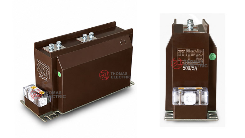
Product Display


Applications
- Indoor 10kV, 11kV and 12kV class metal-clad switchgear
- Incoming feeder panels requiring metering, measurement and protection in one CT
- Main feeder cabinets requiring multiple relay protection circuits
- Energy metering systems requiring dedicated metering secondary cores
- Substation automation, SCADA and power quality monitoring systems
- Projects requiring AS12/175b/4S multi-secondary CT replacement or standardization
Features
- 175b support body: The 175b structure provides a balanced body width for medium-voltage switchgear where terminal space and mechanical support are both important.
- 4S multi-secondary layout: The 4S schematic supports multiple secondary circuits, making the CT suitable for combined metering, measurement and protection systems.
- IEC-style voltage coordination: The 12/42/75kV insulation level fits common international 10kV, 11kV and 12kV class distribution networks.
- Metering and protection accuracy: Typical combinations include 0.2S, 0.2, 0.5, 10P, 10P15, 10P20 and 10P30 according to project requirements.
- Wide current selection: The sample data covers low-current and high-current ranges up to 2500A, with special requirements subject to technical agreement.
- Separated secondary functions: Different secondary cores can be assigned to billing metering, measurement display, feeder protection and backup relay protection.
Principle
The LZZBJ9-12/175b/4S current transformer works by electromagnetic induction. Primary current produces magnetic flux in the CT magnetic core, and each secondary winding delivers a proportional low-current output to connected devices. The epoxy resin insulation separates the medium-voltage primary circuit from the low-voltage secondary circuits and helps maintain reliable insulation under indoor operating conditions.
For the 4S configuration, each secondary circuit should be treated as an independent functional core. Metering cores require stable ratio accuracy and phase displacement under rated burden, while protection cores require sufficient accuracy limit performance under fault current. During selection, rated output, accuracy class, protection factor, short-time thermal current and dynamic current must be reviewed together.
Model Designation

The model code can be interpreted as follows:
| Code | Meaning |
|---|---|
| L | Current transformer |
| Z | Indoor type / support structure |
| Z | Epoxy resin casting insulation |
| B | Protection level available |
| J | Strengthened design |
| 9 | Design serial number |
| 12 | 12kV class maximum operating voltage |
| 175b | Nominal width / structure dimension code |
| 4S | Multi-secondary schematic code for four secondary functions |
| AS12 | Alternative IEC-style 12kV series designation for the same CT platform |
Technical Data
| Item | Specification |
|---|---|
| Rated voltage class | 10kV, 11kV and 12kV class indoor systems |
| Rated insulation level | 12/42/75kV |
| Rated frequency | 50Hz / 60Hz |
| Rated primary current | 1A to 2500A reference range according to sample data; special ratios subject to agreement |
| Rated secondary current | 5A or 1A |
| Accuracy combination | 0.2S/10P, 0.2S/10P15, 0.2S/10P20, 0.2S/10P30, 0.5/10P, 0.5/10P15, 0.5/10P20, 0.5/10P30 and project-specific combinations |
| Rated output | 10/15/30, 10/20/30, 15/20/30, 20/30/30, 30/30/30 or project-specific VA configuration |
| Ambient temperature | -5°C to +40°C |
| Insulating medium | Epoxy resin |
| Installation type | Indoor support-type / switchgear installation |
| Applicable standards | GB 20840.2-2014, IEC 61869-2:2012 and special project requirements |
Terminals
The 4S schematic structure indicates a multi-secondary arrangement. The product may be supplied with several independent secondary circuits for metering, measurement, protection and backup protection. Typical terminal markings include P1 / P2 for the primary side and 1S1 / 1S2, 2S1 / 2S2, 3S1 / 3S2 and 4S1 / 4S2 for secondary cores. Final marking shall follow the approved drawing and nameplate.
| Terminal Marking |
Function | Application Note |
|---|---|---|
| P1 / P2 | Primary terminals | Primary current direction and busbar connection shall follow the wiring diagram. |
| 1S1 / 1S2 | First secondary core | Usually assigned to metering or precision measurement. |
| 2S1 / 2S2 | Second secondary core | Usually assigned to measurement display or monitoring. |
| 3S1 / 3S2 | Third secondary core | Usually assigned to feeder relay protection. |
| 4S1 / 4S2 | Fourth secondary core | Used for backup protection, additional relay function or project-specific circuit. |
Selection Table
The following table is arranged by rated primary current range and typical multi-core accuracy combinations. Long accuracy and rated-output values are wrapped into multiple lines to keep the table readable in responsive layouts.
| Rated
Primary Current (A) |
Accuracy
Class Combination |
Rated
Output(VA) |
Short-Time
Thermal Current |
Rated
Dynamic Current (kA) |
|---|---|---|---|---|
| 1 | 0.2S / 10P 0.2S / 10P15 0.2S / 10P20 0.2S / 10P30 0.5 / 10P 0.5 / 10P15 0.5 / 10P20 0.5 / 10P30 |
10 / 15 / 30 10 / 20 / 30 10 / 20 / 40 |
1.0kA | 2.5 |
| 20, 30, 40 50, 75, 100 |
150 × I1n | 375 × I1n | ||
| 150, 200 | 31.5kA | 80 | ||
| 300, 400 | 45kA | 112.5 | ||
| 500 | 63kA | 130 | ||
| 600, 800 | 10 / 20 / 30 15 / 20 / 40 20 / 30 / 30 30 / 30 / 30 |
63kA | 130 | |
| 1000, 1200, 1250 | 80kA | 160 | ||
| 1500 | 100kA | 160 | ||
| 2000 | 100kA | 160 | ||
| 2500 | 100kA | 160 |
Note: The above values are for technical selection reference. If project requirements exceed the listed range, final parameters shall be confirmed by agreement between manufacturer and purchaser. Nameplate data, approved drawings and factory test reports shall prevail.
Structure Reference
| Structure | Application Reference |
Selection Note |
|---|---|---|
| 175b | Medium-width support structure | Suitable for switchgear requiring balanced body size, terminal clearance and mechanical strength. |
| 4S | Four-secondary schematic arrangement | Used when several independent secondary circuits are required in one CT body. |
| AS12 | IEC-style 12kV designation | Can be used with LZZBJ9-12/175b/4S in product naming, export documents and project selection. |
Service Conditions
- Installation location: indoor medium-voltage switchgear
- System voltage: 10kV, 11kV and 12kV class networks
- Rated frequency: 50Hz / 60Hz
- Ambient temperature: -5°C to +40°C
- The installation environment should be free from severe vibration, conductive dust, corrosive gas, explosive medium, heavy pollution and abnormal condensation.
- For high altitude, humid, coastal, high-pollution or special switchgear conditions, technical confirmation is required before ordering.
Standards and Compliance
The LZZBJ9-12/175b/4S current transformer can be supplied according to GB 20840.2-2014, IEC 61869-2:2012 and special project requirements. For IEC-oriented international projects, the product can be positioned as a 12kV class indoor epoxy cast-resin CT with 12/42/75kV insulation coordination. Routine tests normally include ratio test, polarity verification, accuracy test, dielectric withstand test and appearance inspection.
Installation and Dimensions

The product adopts an indoor support-type structure with top primary terminals and lower secondary terminal arrangement. Compared with 2S designs, the 4S version requires more attention to secondary terminal identification and wiring space because more secondary circuits are involved. The approved drawing shall be used before switchgear production or replacement.
Dimensions
| Item | Dimension / Note |
|---|---|
| Structure code | 175b support-type design |
| Secondary schematic | 4S multi-secondary arrangement |
| Primary terminal arrangement | Confirmed according to current ratio and approved drawing |
| Secondary terminal arrangement | Multiple secondary terminals arranged according to 4S schematic |
| Mounting holes | Confirmed according to outline drawing |
| Drawing confirmation | Required before switchgear production or replacement |
Safety Notes
- Confirm model, current ratio, secondary current, accuracy combination, rated output and insulation level before installation.
- Check mounting space, busbar connection, primary terminal position, secondary terminal layout and phase clearance before assembly.
- Verify every secondary terminal marking before wiring, especially when four secondary circuits are supplied.
- Connect P1/P2 and secondary terminals according to polarity markings and the project wiring diagram.
- The secondary circuit of a current transformer must not be open-circuited when the primary circuit is energized.
- Before disconnecting meters or relays, short-circuit the corresponding secondary circuit through an approved shorting terminal block.
- Installation and maintenance shall be performed by qualified medium-voltage electrical personnel.
Ordering Info
- Product model: LZZBJ9-12/175b/4S or AS12/175b/4S
- Rated primary current and rated secondary current
- Accuracy class combination and rated output for each secondary core
- Rated insulation level and applicable IEC / GB standard
- Required short-time thermal current and dynamic current
- Secondary core quantity, 4S schematic code and terminal marking requirement
- Switchgear layout, mounting dimensions and primary terminal direction
- Quantity, certificates, routine test reports, labeling and packaging requirements
Selection Guide
- Confirm model name: Use LZZBJ9-12/175b/4S or AS12/175b/4S according to the project document and nameplate requirement.
- Define four secondary functions: Assign each secondary core to metering, measurement, feeder protection, backup protection or monitoring.
- Select current ratio: Choose rated primary current according to feeder load, metering range and relay setting.
- Check accuracy and burden: Confirm the accuracy class and rated output for every secondary core separately.
- Verify fault withstand: Rated short-time thermal current and dynamic current shall meet the switchgear short-circuit level.
- Review wiring space: Check secondary terminal space and cable routing because 4S configurations involve more wiring points.
- Approve drawings: Confirm primary terminal layout, busbar spacing, mounting holes and secondary markings before production.