Product Overview
The JDZ1-1 / JDZ2-1 indoor low-voltage potential transformer is a cast-resin insulated voltage transformer designed for indoor power systems with rated frequency of 50Hz or 60Hz and rated voltage up to 1kV. It is used to convert primary voltage into a standard 100V secondary voltage signal for electrical energy metering, voltage monitoring, voltage control, and relay protection applications.
The JDZ1-1 and JDZ2-1 series are suitable for low-voltage switchgear, metering panels, distribution cabinets, and power monitoring systems. The product adopts a resin-cast insulation structure with silicon steel sheet core and primary / secondary windings, providing compact construction, indoor insulation performance, and stable output for measurement and protection circuits.
Product Type
| Item | Specification |
|---|---|
| Product name | Indoor Low Voltage Potential Transformer |
| Model series | JDZ1-1 / JDZ2-1 |
| Product structure | Indoor cast-resin insulated voltage transformer |
| Rated voltage class | 1kV and below low-voltage AC system |
| Rated frequency | 50Hz / 60Hz |
| Rated voltage ratio | 380,660/100V; 660,1140/100V; 750,1500/100V |
| Installation location | Indoor |
| Typical applications | Voltage measurement, electric energy metering, voltage control, relay protection |
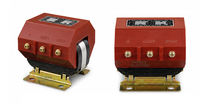
Product Display


Main Applications
- Indoor low-voltage AC power systems rated up to 1kV
- Voltage measurement circuits in distribution systems
- Electrical energy metering and power monitoring panels
- Voltage control circuits in low-voltage switchgear
- Relay protection circuits requiring isolated voltage signals
- Distribution cabinets, metering cabinets, and industrial control panels
Key Technical Features
- Indoor cast-resin insulation: The transformer body is cast insulated to support dielectric strength and mechanical stability.
- Low-voltage potential transformer design: Suitable for voltage measurement, metering, voltage control, and relay protection in systems up to 1kV.
- Standard 100V secondary output: Designed for connection to common meters, instruments, relays, and monitoring devices.
- Multiple voltage ratio options: Common ratios include 380,660/100V, 660,1140/100V, and 750,1500/100V.
- Compact indoor installation: Fixed mounting structure for low-voltage panels and switchgear applications.
- Standards compliance: Designed with reference to IEC 60044-2 and GB 1207 requirements for voltage transformer applications.
Working Principle
The JDZ1-1 / JDZ2-1 potential transformer operates according to electromagnetic induction. The primary winding is connected to the measured low-voltage circuit, and the secondary winding outputs a proportional voltage signal, normally 100V, for meters, relays, and measuring instruments. This allows the primary circuit voltage to be measured safely while maintaining electrical isolation between primary and secondary circuits.
Model Designation

The model code can be interpreted as follows:
| Code | Meaning |
|---|---|
| J | Voltage transformer / potential transformer |
| D | Indoor application |
| Z | Cast-resin insulated structure |
| 1 / 2 | Design number or product structure code |
| 1 | Rated voltage class: 1kV |
Technical Data
| Item | Specification |
|---|---|
| Rated voltage class | 1kV and below |
| Rated frequency | 50Hz / 60Hz |
| Rated voltage ratio | 380,660/100V; 660,1140/100V; 750,1500/100V |
| Rated secondary voltage | 100V |
| Rated output | 25VA according to catalogue data |
| Accuracy class | Class 5 according to catalogue data; project-specific accuracy requirements can be confirmed by agreement |
| Load power factor | cosφ = 0.8 lagging |
| Insulation level | 0.66/3.6kV, 1.14/3.6kV, 1.5/3.6kV according to selected voltage ratio |
| Dielectric withstand | 3kV, 1 minute between primary, secondary, and ground according to catalogue description |
| Installation location | Indoor |
| Applicable standards | IEC 60044-2, GB 1207-2006, GB 1207-75; project-specific requirements can be confirmed by agreement |
Insulation Reference
| Rated Voltage
Ratio (V) |
Rated
Frequency (Hz) |
Rated
Output (VA) |
Accuracy
Class |
Insulation
Level (kV) |
|---|---|---|---|---|
| 380,660/100 | 50 | 25 | 5 | 0.66/3.6 |
| 660,1140/100 | 50 | 25 | 5 | 1.14/3.6 |
| 750,1500/100 | 50 | 25 | 5 | 1.5/3.6 |
Note: Special voltage ratios, environmental requirements, and installation parameters can be confirmed through technical agreement before ordering.
Service Conditions
- Installation location: indoor
- System voltage: 1kV and below
- Rated frequency: 50Hz / 60Hz
- Suitable for indoor power systems and low-voltage distribution equipment
- The product can be applied in humid and tropical regions when specified by project requirements.
- The installation environment should be free from severe vibration, corrosive gas, explosive medium, conductive dust, and heavy pollution.
- For special humidity, temperature, altitude, pollution level, or cabinet layout requirements, technical confirmation is recommended before ordering.
Standards & Compliance
The JDZ1-1 / JDZ2-1 indoor low-voltage potential transformer can be supplied according to IEC 60044-2, GB 1207-2006, and related project requirements. The catalogue also references GB 1207-75 voltage transformer requirements. Final standards, routine test items, nameplate data, and acceptance documents should be confirmed in the technical agreement.
Installation & Dimensions

The JDZ1-1 / JDZ2-1 series adopts a compact cast-resin insulated structure for indoor fixed installation. The primary and secondary terminals are arranged on the transformer body for convenient connection. Final outline and mounting dimensions should be confirmed according to the approved drawing before cabinet design or batch ordering.
Outline & Installation Reference
| Item | Reference Value / Description |
|---|---|
| Product structure | Cast-resin insulated indoor potential transformer |
| Installation method | Indoor fixed mounting |
| Primary terminal marking | A and X |
| Secondary terminal marking | a and x |
| Overall dimension reference | Refer to approved outline drawing before cabinet layout |
Unit: mm for dimensional drawings. Final dimensions are subject to confirmed drawing and selected specification.
Connection & Wiring Notes
- Connect primary terminals according to the marked symbols A and X.
- Connect secondary terminals according to the marked symbols a and x.
- Confirm the voltage ratio, insulation level, rated output, and accuracy class before wiring.
- The secondary circuit should be connected to suitable meters, relays, or measuring instruments according to the project wiring diagram.
- Secondary wiring, grounding, and terminal protection should comply with the project specification and local electrical regulations.
Installation & Safety Notes
- Confirm the product model, voltage ratio, insulation level, rated output, and installation dimensions before installation.
- Install the voltage transformer in an indoor location suitable for low-voltage electrical equipment.
- Do not operate the voltage transformer beyond its rated output or specified insulation level.
- Check terminal tightening, secondary wiring, and grounding before energizing.
- Installation and maintenance should be performed by qualified electrical personnel.
Ordering Information
Please provide the following information when ordering or requesting a quotation:
- Product model: JDZ1-1 or JDZ2-1
- Rated voltage ratio, such as 380,660/100V, 660,1140/100V, or 750,1500/100V
- Insulation level
- Rated output and required accuracy class
- Rated frequency and operating environment
- Test specification or applicable standard
- Quantity and application, such as metering, voltage control, or relay protection
- Special requirements for terminals, labels, drawings, inspection documents, certificates, or packaging
Selection Guidelines
- Confirm system voltage: Select JDZ1-1 / JDZ2-1 for indoor low-voltage AC systems rated up to 1kV.
- Confirm voltage ratio: Choose the primary and secondary voltage ratio according to the measured circuit and connected instrument requirement.
- Confirm insulation level: Match the insulation level with the system voltage and project safety requirement.
- Confirm rated output: The connected burden of meters, relays, instruments, and wiring should not exceed the rated output.
- Confirm application: Determine whether the transformer is used for metering, voltage control, or relay protection.
- Confirm installation space: Check the outline drawing, terminal position, and cabinet clearance before production or batch installation.