Product Overview
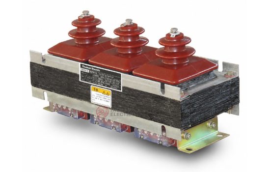
The JSZW3-6G / JSZW3-10G three-phase voltage transformer is an indoor epoxy cast-resin voltage transformer developed for mining flameproof combined switchgear and mine-duty medium-voltage power distribution equipment. It is used for voltage measurement, voltage indication, energy metering reference, control power signal acquisition and relay protection in three-phase AC systems with rated frequency of 50Hz or 60Hz.
This product should be positioned differently from the standard JSZW3-6 / JSZW3-10 indoor switchgear voltage transformer. The key application of the G type is mining flameproof combined switch assemblies, where compact installation, vibration tolerance, switch mechanism integration, terminal accessibility and stable voltage signal output are more important than general cabinet interchangeability. The product is installed inside mine-duty combined switch equipment and provides voltage signals for the electrical control, metering and protection circuit of the complete switch assembly.
For international product pages, the voltage class can be expressed as 6kV, 10kV, 11kV and 12kV class. The catalogue model uses JSZW3-6G and JSZW3-10G, while export project documentation may include 11kV and 12kV class wording according to the system voltage, insulation level and project specification. The product follows an epoxy cast-resin indoor structure and is supplied with vertical or horizontal installation arrangements to match different flameproof switch structures.
Product Type
| Item | Specification |
|---|---|
| Product name | Mining Flameproof Combined Switch Three-Phase Epoxy Cast-Resin Voltage Transformer |
| Model series | JSZW3-6G / JSZW3-10G / JSZW3-11G / JSZW3-12G |
| Product structure | Three-phase integrated epoxy cast-resin voltage transformer for mining combined switchgear |
| Voltage class | 6kV, 10kV, 11kV and 12kV class medium-voltage systems |
| Rated frequency | 50Hz / 60Hz |
| Typical voltage ratio | 6000/100V or 10000/100V; 11000/110V and 12000/110V can be confirmed by project requirement |
| Accuracy class | 0.2 / 6P(3P), 0.5 / 6P(3P), 1 / 6P(3P) |
| Limit output | 600VA reference |
| Installation form | Vertical installation or horizontal installation |
| Typical application | Mining flameproof combined switch, voltage measurement, control signal, protection and monitoring circuit |
Product Display

Applications
- Mining flameproof combined switchgear
- Mine-duty medium-voltage distribution and control equipment
- 6kV, 10kV, 11kV and 12kV class indoor power systems
- Voltage measurement and indication circuits inside combined switch assemblies
- Relay protection, undervoltage protection, overvoltage protection and monitoring circuits
- Control power reference and signal acquisition for mine electrical equipment
- Projects requiring vertical or horizontal transformer installation inside compact switchgear compartments
Features
- Mining combined-switch application: Different from general switchgear VTs, the JSZW3-G series is designed around the installation and wiring needs of mining flameproof combined switch assemblies.
- Three-phase integrated structure: One compact unit provides three-phase voltage transformation, helping reduce wiring and installation space inside the switch body.
- Epoxy cast-resin insulation: The cast structure supports insulation stability, mechanical strength and indoor service reliability.
- Vertical and horizontal installation: Two mechanical arrangements are available to match different mining switch layouts and internal compartment structures.
- Metering and protection output: Accuracy combinations such as 0.2/6P(3P), 0.5/6P(3P) and 1/6P(3P) support both measurement and protection circuits.
- International voltage expression: The product can be documented for 6kV, 10kV, 11kV and 12kV class systems for export projects.
Working Principle
The JSZW3-G voltage transformer works according to electromagnetic induction. The primary winding is connected to the medium-voltage three-phase circuit, and the secondary winding outputs a reduced voltage signal for measuring instruments, protection relays, control circuits and monitoring devices. The output voltage is isolated from the primary high-voltage circuit, allowing safe signal acquisition in the combined switch control system.
In mining flameproof combined switch applications, the VT is often part of the control and protection chain of the complete switch assembly. Therefore, the selection should not only consider the rated voltage ratio and accuracy class, but also the installation direction, terminal position, cabinet clearance, wiring diagram, vibration environment and maintenance accessibility.
Model Designation

| Code | Meaning |
|---|---|
| J | Voltage transformer / potential transformer |
| S | Three-phase configuration |
| Z | Epoxy resin casting insulation |
| W | Voltage transformer structure code |
| 3 | Design sequence code |
| 6 / 10 / 11 / 12 | Rated voltage class reference in kV |
| G | Mining flameproof combined-switch application type |
| Vertical / Horizontal | Installation arrangement according to switchgear internal layout |
Technical Data
| Item | Specification |
|---|---|
| Model series | JSZW3-6G / JSZW3-10G / JSZW3-11G / JSZW3-12G |
| Rated voltage class | 6kV, 10kV, 11kV and 12kV class systems |
| Rated insulation level | 7.2/30/60kV for 6kV class; 12/42/75kV for 10kV, 11kV and 12kV class by project confirmation |
| Rated frequency | 50Hz / 60Hz |
| Ambient temperature | -25°C to +40°C |
| Voltage transformer type | Three-phase epoxy cast-resin inductive voltage transformer |
| Rated voltage ratio | 6000/100V, 10000/100V, 11000/110V or project-specified ratio |
| Accuracy class | 0.2 / 6P(3P), 0.5 / 6P(3P), 1 / 6P(3P) |
| Limit output | 600VA reference |
| Applicable standards | IEC 61869-3, IEC 61869-1, GB/T 20840.3-2013, IEC 61869-3:2011 and project-specific requirements |
Selection Table
The table below is adapted for website display and international project selection. Long headers and cells are split into multiple lines to keep the layout suitable for responsive pages.
| Model | Rated Voltage Ratio |
Accuracy Class and Rated Output |
Limit Output (VA) |
Rated Insulation Level |
|---|---|---|---|---|
| JSZW3-6G | 6000 / 100V | 0.2 / 6P(3P): 3 × 15 / 100VA | 600 | 7.2 / 30 / 60kV |
| 0.5 / 6P(3P): 3 × 30 / 100VA | ||||
| 1 / 6P(3P): 3 × 50 / 100VA | ||||
| JSZW3-10G | 10000 / 100V | 0.2 / 6P(3P): 3 × 15 / 100VA | 600 | 12 / 42 / 75kV |
| 0.5 / 6P(3P): 3 × 30 / 100VA | ||||
| 1 / 6P(3P): 3 × 50 / 100VA | ||||
| JSZW3-11G | 11000 / 110V or project-specified ratio |
0.2 / 3P or 0.2 / 6P by agreement | 600 reference | 12 / 42 / 75kV by confirmation |
| 0.5 / 3P or 0.5 / 6P by agreement | ||||
| 1 / 3P or 1 / 6P by agreement | ||||
| JSZW3-12G | 12000 / 110V or project-specified ratio |
0.2 / 3P or 0.2 / 6P by agreement | 600 reference | 12 / 42 / 75kV by confirmation |
| 0.5 / 3P or 0.5 / 6P by agreement | ||||
| 1 / 3P or 1 / 6P by agreement |
Note: Rated output and accuracy class are selected as matched combinations. If the user’s data go beyond the catalogue range, final parameters may be determined by technical agreement between manufacturer and purchaser.
Installation Variants
| Variant | Structure | Application Note |
|---|---|---|
| Vertical installation | Upright mounting arrangement inside the combined switch assembly | Suitable where cabinet height and vertical terminal access are available. |
| Horizontal installation | Low-profile mounting arrangement inside the switch compartment | Suitable where height is limited and the transformer must be arranged along the equipment base. |
| Customized installation | Terminal direction, mounting hole and bracket arrangement by drawing | Recommended for complete mining switch OEM projects. |
Windings
The JSZW3-G series normally includes a three-phase primary winding and secondary windings for measurement and protection. Typical primary terminals are marked A, B, C and N. Secondary terminals may be marked a, b, c, n, and the residual or protection winding may be marked da / dn according to the wiring diagram.
| Winding / Terminal | Function | Engineering Note |
|---|---|---|
| A, B, C | Primary phase terminals | Connected to the medium-voltage three-phase circuit. |
| N | Primary neutral terminal | Connection depends on the transformer wiring and system grounding arrangement. |
| a, b, c, n | Secondary voltage terminals | Used for instruments, meters, control and monitoring devices. |
| da / dn | Protection or residual-voltage output | Used where residual-voltage or protection signal output is required. |
Wiring Diagram

The catalogue shows a Y / Δ connection arrangement for the three-phase voltage transformer. The final wiring method should be confirmed according to the combined switch control circuit, voltage monitoring requirement, protection scheme and terminal drawing. For mining combined switch applications, the wiring diagram should be reviewed together with the complete switchgear schematic.
Service Conditions
- Installation location: indoor mining flameproof combined switchgear
- Rated frequency: 50Hz / 60Hz
- Ambient temperature: -25°C to +40°C
- Suitable for mine-duty switchgear compartments and compact electrical assemblies
- The installation environment should be free from direct water ingress, severe conductive pollution and insulation-damaging chemical vapor.
- For underground mine environments, vibration, humidity, condensation and flameproof enclosure compatibility should be confirmed by the complete equipment manufacturer.
Standards and Compliance
The JSZW3-G series voltage transformer can be specified according to IEC 61869-3 for inductive voltage transformers and IEC 61869-1 for general instrument transformer requirements. Catalogue references also include GB/T 20840.3-2013 and IEC 61869-3:2011. For mining combined switch applications, the complete switchgear manufacturer should also confirm the applicable mine-duty equipment standard, flameproof enclosure design and project acceptance requirements.
Installation and Dimensions

The JSZW3-G series is supplied in vertical and horizontal installation forms. Before production, the complete switch OEM should confirm the mounting hole positions, transformer height, phase bushing clearance, secondary terminal direction, wiring diagram, grounding method and maintenance access. This product is not only selected by voltage ratio; it must also be matched with the mechanical structure of the mining flameproof combined switch.
Safety Notes
- Confirm voltage class, voltage ratio, insulation level, accuracy class and rated output before production.
- Check whether the switch assembly requires vertical or horizontal installation.
- Confirm terminal direction and secondary wiring before designing the complete switch control circuit.
- Secondary circuits of voltage transformers shall not be short-circuited during operation.
- Before maintenance, de-energize the primary circuit and follow lockout/tagout safety procedures.
- One point of the secondary circuit should be grounded according to project electrical safety practice.
- Installation and commissioning shall be performed by qualified medium-voltage electrical personnel