Product Overview
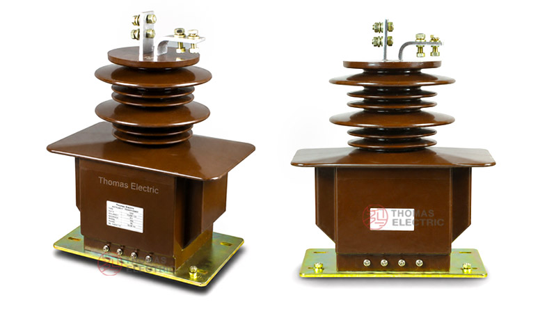
The LCZ-35G / LZZB7-35 indoor single-phase epoxy resin cast current transformer is a medium-voltage support-type current transformer designed for 35kV / 36kV / 40.5kV indoor AC power systems. It is used for current measurement, energy metering and relay protection in systems with rated frequency of 50Hz or 60Hz. The product adopts epoxy resin casting insulation, with the current transformer body fully enclosed to provide stable insulation performance, moisture resistance and reliable mechanical strength for indoor switchgear applications.
This product is different from the previous 250mm-width LZZBJ9-35 platform. The model shown in the catalogue is LCZ-35G/270f/2 (LZZB7-35), where 270f can be treated as a structural size / body-width platform code for the LCZ-35G series. For website positioning, the main product title should use LCZ-35G (LZZB7-35), while the detailed model can mention LCZ-35G/270f/2. It is suitable for 35kV-class indoor switchgear where a compact single-phase epoxy CT is required, with international voltage expression written as 35kV / 36kV / 40.5kV and insulation level 40.5/95/185kV.
Product Type
 Indoor Single-Phase Epoxy Resin Cast Current Transformer Thomas Electric")
 Indoor Single-Phase Epoxy Resin Cast Current Transformer Thomas Electric")
| Item | Specification |
|---|---|
| Product name | Indoor Single-Phase Epoxy Resin Cast Current Transformer |
| Main model | LCZ-35G / LZZB7-35 |
| Detailed model reference | LCZ-35G/270f/2 (LZZB7-35) |
| Installation condition | Indoor |
| Phase | Single phase |
| Structure | Fully enclosed support-type / pillar-type epoxy resin cast structure |
| Application | Current measurement, energy metering and relay protection |
| System voltage class | 35kV / 36kV / 40.5kV |
| Rated insulation level | 40.5/95/185kV |
| Rated frequency | 50Hz or 60Hz |
| Rated secondary current | 5A or 1A |
| Typical installation | Indoor switchgear, air-insulated switchgear and power metering cabinet |
Model Explanation
 Indoor Single-Phase Epoxy Resin Cast Current Transformer Thomas Electric")
Applications
- 35kV, 36kV and 40.5kV indoor medium-voltage AC power systems
- Indoor single-phase current measurement circuits
- Air-insulated switchgear and indoor distribution cabinets
- Energy metering and power measurement panels
- Relay protection for feeder, transformer and bus-section circuits
- Industrial substations, utility substations and power distribution rooms
- Projects requiring a compact support-type epoxy CT for 35kV-class switchgear
- Medium-voltage systems requiring separate metering and protection secondary windings
Features
- 35kV-class indoor CT: Designed for 35kV / 36kV / 40.5kV medium-voltage switchgear systems.
- Single-phase epoxy cast design: Suitable for indoor switchgear where phase-by-phase CT installation is required.
- Fully enclosed structure: The winding and core assembly is sealed inside the epoxy resin body to improve insulation reliability.
- 40.5/95/185kV insulation level: Supports international 40.5kV equipment insulation coordination.
- Metering and protection functions: Supports current measurement, energy metering and relay protection in one CT platform.
- Moisture-resistant insulation: Epoxy resin casting improves resistance to indoor humidity and surface contamination.
- Switchgear-friendly layout: Bottom mounting base, upper primary terminals and lower secondary terminal area support cabinet integration.
- Customizable parameters: Current ratio, accuracy class, rated output and terminal arrangement can be confirmed according to project requirements.
Structure Overview
The LCZ-35G / LZZB7-35 current transformer adopts an indoor single-phase epoxy resin casting structure. The upper part forms the high-voltage insulation and primary terminal area, while the lower part contains the enclosed CT body, secondary terminal area and mounting base. This structure is suitable for 35kV-class indoor switchgear where reliable insulation distance and compact cabinet layout are both required.
The primary outlet terminals are marked P1 and P2. Secondary terminals are arranged according to the number of secondary windings, normally with markings such as 1S1 / 1S2 and 2S1 / 2S2. The final terminal arrangement shall follow the approved wiring diagram and product nameplate.
Technical Data
| Parameter | Specification |
|---|---|
| Main model | LCZ-35G / LZZB7-35 |
| Detailed model reference | LCZ-35G/270f/2 (LZZB7-35) |
| Product type | Indoor single-phase epoxy resin cast current transformer |
| System voltage class | 35kV / 36kV / 40.5kV |
| Rated insulation level | 40.5/95/185kV |
| Rated frequency | 50Hz or 60Hz |
| Rated secondary current | 5A or 1A |
| Rated primary current range | 15A to 1000A reference according to catalogue table; other ratios by agreement |
| Typical accuracy combinations | 0.2S/0.5, 0.2/0.5/10P10, 0.2/0.5/10P15, 10P10/10P10, 10P15/10P15 |
| Rated output | 30/50VA, 30/30VA, 30/20VA, 20/20VA, 15/15VA and other combinations according to ratio and accuracy class |
| Ambient temperature | -5°C to +40°C |
| Applicable standards | IEC 61869-1, IEC 61869-2, GB/T 20840.1, GB/T 20840.2; legacy IEC 60044-1 / GB1208 references by agreement |
Selection Table
The following selection table is reorganized from the supplied catalogue information and optimized for website display. Long headings and accuracy-class cells are split into multiple lines to reduce overflow on product pages.
| Rated
Primary |
Accuracy
Class |
Rated
Output |
Short-Time ThermalCurrent |
Rated
Dynamic |
|---|---|---|---|---|
| 15 | 0.2S / 0.5 0.2 / 0.5 / 10P10 0.2 / 0.5 / 10P15 10P10 / 10P10 10P15 / 10P15 |
30 / 50 30 / 30 30 / 20 20 / 20 15 / 15 |
3kA | 7.5kA |
| 20 | 4kA | 10kA | ||
| 30 | 6kA | 15kA | ||
| 40 | 8kA | 20kA | ||
| 50 | 10kA | 25kA | ||
| 75 | 15kA | 37.5kA | ||
| 100 | 21kA | 52.5kA | ||
| 150 | 31.5kA | 78.75kA | ||
| 200 | 0.2S / 0.5 0.2 / 0.5 / 10P10 0.2 / 0.5 / 10P15 0.2 / 0.5 / 10P20 10P10 / 10P10 10P15 / 10P15 |
50 / 50 50 / 30 50 / 20 50 / 15 30 / 30 20 / 25 |
45kA | 112.5kA |
| 300 | 63kA | 157.5kA | ||
| 400 | 63kA | 157.5kA | ||
| 500, 600, 800 | 63kA | 157.5kA | ||
| 1000 | 80kA | 200kA |
Note: If required parameters exceed the above reference range, they can be confirmed by technical agreement between manufacturer and purchaser. Final values shall follow the approved drawing, nameplate and factory test report.
Operating Conditions
- Installation: Indoor installation for 35kV / 36kV / 40.5kV switchgear and distribution systems.
- Rated frequency: 50Hz or 60Hz.
- Ambient temperature: -5°C to +40°C.
- Humidity: Indoor environment without severe condensation; special humidity requirements should be confirmed by project agreement.
- Altitude: Standard indoor service; high-altitude applications require insulation coordination confirmation.
- Site condition: No severe vibration, shock or mechanical impact at the installation site.
- Air quality: Ambient air should not be seriously polluted by dust, smoke, corrosive gases, vapours or salt.
- Maintenance: Keep the resin surface clean and dry to maintain insulation performance.
Installation and Dimensions
 Indoor Single-Phase Epoxy Resin Cast Current Transformer Thomas Electric")
The LCZ-35G / LZZB7-35 is installed inside 35kV-class indoor switchgear or distribution cabinets. The base, primary terminal direction, secondary terminal position and insulation clearance must be checked against the approved outline drawing before installation. The catalogue drawing shows different terminal connection structures for 5A ≤ I1n ≤ 500A and 600A ≤ I1n ≤ 1000A, so the final drawing should be confirmed according to the selected primary current ratio.
| Installation Item | Recommended Check Point |
|---|---|
| Mounting base | Confirm base size, hole spacing, support strength and grounding position before installation. |
| Primary terminals | Check P1 / P2 direction, conductor connection method and phase-to-ground clearance. |
| Secondary terminal area | Reserve access space for wiring, testing, inspection and terminal marking. |
| Switchgear clearance | Confirm insulation clearance according to the 40.5kV equipment class. |
| Current range layout | Use the correct terminal structure for the selected current range. |
| Grounding | Ground one point of the secondary circuit and connect the equipment grounding point according to project design. |
| Drawing confirmation | Use the approved outline drawing and terminal diagram for final production and installation. |
Windings & Terminal Marking
The primary terminals are identified as P1 and P2. Secondary winding terminals are marked according to the number of secondary outputs, such as 1S1 / 1S2 for the measurement winding and 2S1 / 2S2 for the protection winding. The final marking shall follow the wiring diagram and product nameplate.
| Terminal | Function | Application Note |
|---|---|---|
| P1 / P2 | Primary terminals | Used for primary current direction and polarity reference. |
| 1S1 / 1S2 | First secondary winding | Usually assigned to metering or measurement circuit. |
| 2S1 / 2S2 | Second secondary winding | Usually assigned to relay protection circuit. |
| Additional S terminals | Extra secondary winding groups | Used for multi-core measurement or protection circuits according to project design. |
| Grounding point | Secondary circuit grounding reference | One point of the secondary circuit should be grounded according to project practice. |
Standards and Compliance
For international product pages, the LCZ-35G / LZZB7-35 should be specified according to IEC 61869-1 and IEC 61869-2. GB-based documentation can refer to GB/T 20840.1 and GB/T 20840.2. Older catalogue references such as IEC 60044-1 and GB1208 may be retained for legacy tender compatibility, but modern documentation should use IEC 61869 and GB/T 20840 series as the preferred standard language.
Selection Guide
- Confirm voltage level: Use this product for 35kV / 36kV / 40.5kV indoor switchgear systems.
- Confirm model naming: Use LCZ-35G (LZZB7-35) as the main product name; LCZ-35G/270f/2 can be used as the detailed catalogue model.
- Select current ratio: Choose the primary current according to feeder load, metering range and protection setting.
- Choose secondary current: Select 5A for conventional meters and relays, or 1A where lower secondary burden is required.
- Define accuracy class: Use 0.2S / 0.2 / 0.5 for metering and 10P10 / 10P15 / 10P20 or related protection classes for relay protection.
- Check rated burden: Match the CT output with connected meters, relays, terminal blocks and secondary cable length.
- Check terminal structure: Confirm the correct terminal arrangement for the selected primary current range.
- Check short-circuit withstand: Confirm Ith and Idyn against the system fault level.
- Approve drawings: Confirm overall dimensions, terminal arrangement, mounting base and wiring diagram before production.