Product Overview
The LDC-10 / LDC(D)-10 indoor wall-through current transformer is designed for medium-voltage switchgear applications where the primary conductor passes through a cabinet wall, panel, or partition structure. It is used for current measurement, electric energy metering, relay protection, and differential protection in 10kV, 11kV, and 12kV class indoor AC power systems.
The product adopts a single-turn through-type structure with porcelain insulation on the primary conductor and an indoor CT body fixed to the switchgear wall. The LDC-10 version is used for standard measuring and protection circuits, while LDC(D)-10 is configured for differential protection applications. For international projects, this series can be specified with IEC-style 12kV-class insulation coordination, typically using a 12/42/75kV reference insulation level.
Product Type
| Item | Specification |
|---|---|
| Product name | Indoor Wall-Through Type Current Transformer |
| Model series | LDC-10 / LDC(D)-10 |
| Product structure | Indoor single-turn wall-through type current transformer |
| Insulation structure | Porcelain-insulated primary conductor with indoor CT body |
| Voltage class | 10kV, 11kV, and 12kV medium-voltage systems |
| Rated insulation level | 12/42/75kV reference; 10/42/75kV can be used when specified by project data |
| Rated frequency | 50Hz / 60Hz according to project requirement |
| Rated secondary current | 5A standard; 1A can be confirmed by technical agreement |
| Application type | Measurement, metering, relay protection, and differential protection |
| Applicable standard | IEC 61869-1 / IEC 61869-2; IEC 60044-1 can be referenced for legacy projects |
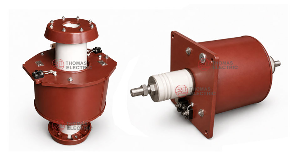
Product Display


Applications
- 10kV, 11kV, and 12kV indoor medium-voltage distribution systems
- Switchgear wall-through or partition-through current measurement points
- Current measurement and electric energy metering circuits
- Relay protection and differential protection circuits
- Incoming and outgoing feeder cabinets requiring through-wall primary connection
- Medium-voltage panels requiring porcelain-insulated primary conductor arrangement
Features
- Wall-through structure: Designed for installation through a switchgear wall, cabinet partition, or panel opening.
- Single-turn primary design: Suitable for higher current feeder applications where the primary conductor passes through the CT structure.
- Porcelain insulation: The primary section uses porcelain insulation for medium-voltage indoor applications.
- Differential protection option: LDC(D)-10 is used when the protection scheme requires differential current input.
- IEC voltage expression: Suitable for 10kV, 11kV, and 12kV systems with 12kV-class insulation coordination.
- Metering and protection output: Secondary output can be configured for measuring class and protection class requirements.
Working Principle
The LDC-10 / LDC(D)-10 current transformer operates according to electromagnetic induction. The primary conductor passes through the transformer body and carries the primary current. The magnetic core and secondary winding generate a proportional secondary current signal for meters, protection relays, or differential protection devices.
For metering applications, the CT must maintain the required ratio accuracy and phase displacement under the rated burden. For protection and differential protection applications, the secondary winding must provide a reliable current signal during fault-current conditions and coordinate with relay settings and short-circuit withstand requirements.
Model Designation

The model designation identifies the current transformer type, single-turn wall-through structure, insulation method, differential protection option, and voltage class.
| Code | Meaning |
|---|---|
| L | Current transformer |
| D | Single-turn through type / wall-through structure |
| C | Porcelain-insulated type |
| (D) | Differential protection configuration |
| 10 | Voltage class identification; suitable for 10kV systems and IEC 12kV-class insulation coordination for 10kV, 11kV, and 12kV projects |
Technical Data
| Item | Specification |
|---|---|
| Rated voltage class | 10kV / 11kV / 12kV medium-voltage systems |
| Highest voltage for equipment | 12kV class according to IEC-style insulation coordination |
| Rated insulation level | 12/42/75kV reference; 10/42/75kV can be used according to original project specification |
| Rated frequency | 50Hz standard; 60Hz available according to project requirement |
| Rated primary current | 600A / 750A / 1000A / 1500A reference range |
| Rated secondary current | 5A standard; 1A can be confirmed by technical agreement |
| Rated output | 10VA for accuracy class 0.5; 15VA for protection class reference |
| Accuracy class | 0.5 for measurement; class B / protection configuration according to project requirement |
| Rated short-time thermal current | 75 × I1n reference |
| Rated dynamic current | 2.5 × Ith reference |
| 10% multiple | 15 reference |
| Installation method | Indoor wall-through / panel-through installation |
| Applicable standard | IEC 61869-1 / IEC 61869-2; IEC 60044-1 can be referenced for legacy specification |
Terminal Marking
The LDC-10 / LDC(D)-10 current transformer uses a wall-through primary conductor arrangement. Secondary terminals are located on the terminal block side of the transformer body and shall be connected according to the approved wiring diagram.
| Terminal Marking | Function | Application Note |
|---|---|---|
| P1 / P2 | Primary current direction | The reference primary current direction is normally defined from P1 to P2 through the wall-through conductor. |
| S1 / S2 | Secondary winding | Used for measurement, metering, or protection signal output according to the selected core configuration. |
| Secondary terminal block | Secondary wiring interface | Located on the side of the CT body for meter, relay, or protection wiring connection. |
| Mounting plate | Wall-through installation interface | Used for fixing the CT to switchgear wall, cabinet partition, or panel structure. |
The secondary circuit must not be open-circuited when the primary circuit is energized. Correct terminal polarity shall be observed to ensure metering accuracy and relay protection performance.
Selection Table
| Primary
Current (A) |
Secondary
Current (A) |
Output
Class 0.5 (VA) |
Output
Protection Class (VA) |
Short-Time
Thermal Current |
Dynamic Current |
10%
Multiple |
|---|---|---|---|---|---|---|
| 600 | 5 | 10 | 15 | 75 × I1n | 2.5 × Ith | 15 |
| 750 | ||||||
| 1000 | ||||||
| 1500 |
Note: The selection table is based on the provided product data for preliminary engineering reference. Final current ratio, secondary current, accuracy class, rated output, insulation level, thermal current, dynamic current, differential protection requirement, terminal layout, and test requirements shall be confirmed according to the approved drawing, nameplate, and factory test report.
Service Conditions
- Installation location: indoor medium-voltage switchgear or wall-through cabinet structure
- System voltage: 10kV, 11kV, or 12kV class
- Rated frequency: 50Hz / 60Hz according to project requirement
- Rated insulation level: 12/42/75kV reference for IEC-style applications
- Installation form: wall-through / partition-through mounting
- The installation environment should be free from severe pollution, corrosive gas, explosive medium, heavy conductive dust, and abnormal condensation.
Standards and Compliance
The LDC-10 / LDC(D)-10 current transformer can be supplied according to IEC 61869-1 and IEC 61869-2. IEC 60044-1 may be referenced for legacy project specifications. Routine tests, dielectric tests, polarity verification, ratio test, accuracy test, insulation resistance, and partial discharge requirements should be confirmed according to the final technical agreement.
Installation and Dimensions

The LDC-10 / LDC(D)-10 series is designed for wall-through indoor installation. The mounting plate, porcelain-insulated primary conductor, secondary terminal block, installation holes, and wall-opening position shall be confirmed according to the approved outline drawing before switchgear design or production.
Outline Data
| Item | Reference Dimension / Note |
|---|---|
| Overall height reference | Approx. 680mm according to provided drawing |
| Wall-through body height reference | Approx. 220–230mm body section reference |
| Primary through section reference | Approx. 496mm between insulation sections according to drawing |
| Mounting plate reference | 314mm × 314mm with 4 × φ14 mounting holes |
| Mounting hole spacing reference | 277mm / 314mm reference layout according to drawing |
| Drawing confirmation | Final outline, wall opening, primary conductor length, mounting dimensions, and terminal position shall be confirmed before production |
Safety Notes
- Confirm the model, voltage class, current ratio, secondary current, accuracy class, burden, insulation level, and differential protection requirement before installation.
- Check wall opening, mounting plate dimensions, primary conductor clearance, secondary terminal access, and grounding arrangement against the approved drawing.
- Connect primary and secondary terminals according to terminal markings and the project wiring diagram.
- The secondary circuit of a current transformer must not be left open when the primary circuit is energized.
- During meter or relay maintenance, short-circuit the CT secondary circuit before disconnecting any secondary wiring.
- Installation and maintenance shall be performed by qualified medium-voltage electrical personnel.
Ordering Info
Please provide the following information when requesting a quotation:
- Product model: LDC-10 or LDC(D)-10
- System voltage: 10kV, 11kV, or 12kV
- Application requirement: measurement, metering, relay protection, or differential protection
- Rated primary current: 600A, 750A, 1000A, 1500A, or project-specific value
- Rated secondary current: 5A or 1A
- Accuracy class and rated output requirement
- Switchgear wall-through layout, mounting plate requirement, and wall opening dimensions
- Primary conductor direction, terminal layout, and required outline drawing
- Quantity, labeling, certificates, routine test reports, and packaging requirements
Selection Tips
- Confirm installation structure: Select this model when the primary conductor must pass through a switchgear wall or cabinet partition.
- Confirm voltage class: Use 12kV-class insulation coordination for 10kV, 11kV, or 12kV medium-voltage applications.
- Confirm current ratio: Select 600A, 750A, 1000A, or 1500A according to feeder load and protection setting range.
- Confirm application type: Use LDC-10 for standard circuits, and LDC(D)-10 where differential protection is required.
- Check wall-opening dimensions: Verify mounting plate size, hole spacing, primary conductor length, and terminal block position before cabinet production.
- Confirm secondary burden: Make sure the connected meter, relay, and wiring burden match the rated output of the CT.