Product Overview
Functional Definition
The LMZ, LMZJ1-0.5 series low-voltage current transformers are precision electromagnetic instruments designed for accurate current measurement, energy metering, and relay protection in low-voltage AC power systems up to 0.66kV. These transformers utilize through-core busbar construction to provide galvanically isolated secondary current signals proportional to primary current.
Key Ratings Snapshot
| Item | Specification (per order / nameplate) |
|---|---|
| System voltage class | 0.66 kV class (low-voltage power distribution applications) |
| Rated frequency | 50 Hz (60 Hz available upon request) |
| Rated secondary current | 5 A |
| Accuracy classes | Metering cores: 0.2, 0.5, 0.2S, 0.5S as specified |
| Rated burden | Per core/winding as specified (VA) |
| Burden power factor | cosφ = 0.8 (lagging) unless otherwise specified |
| Primary current range | 5 A to 5000 A |
| Continuous operation | 110% of rated primary current |
| Dielectric withstand | 3 kV power frequency voltage (1 minute, secondary to ground) |
| Applicable standards | GB/T 20840.2-2014; IEC 61869-2:2012; GB 1208 |
| Mechanical variants | LMZ-0.5 (basic) / LMZJ1-0.5 (extended capacity) |
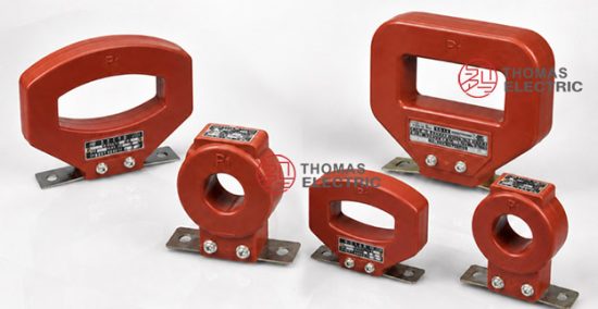
Product Shows

Working Principle
Operating on Faraday’s law of electromagnetic induction, the transformer features a toroidal magnetic core made from cold-rolled oriented silicon steel with primary conductor passing through the central aperture and secondary winding uniformly distributed around the core. The magnetic flux generated by primary current induces proportional voltage in the secondary winding, delivering standardized 5A output current through connected burden.
System Application Position
- Low-Voltage Distribution: 0.4kV-0.66kV power distribution systems and switchgear
- Energy Metering: Commercial and industrial electricity measurement systems
- Protection Circuits: Overcurrent and differential protection schemes in low-voltage networks
- Load Monitoring: Real-time current monitoring in building management systems
Structural Form Overview
Through-core busbar design with cast resin (unsaturated resin) insulation ensures superior electrical performance, moisture resistance, and mechanical strength. The fixed baseplate mounting configuration provides stable installation in low-voltage switchgear and distribution panels while maintaining excellent electrical clearance and safety margins.
Model Designation

Model Code Explanation
- L — Current transformer (CT)
- M — Busbar type (through-core construction)
- Z — Cast-resin (epoxy/unsaturated resin) insulated structure
- J — Extended capacity (LMZJ1 variant only)
- 1 — Design code / iteration (LMZJ1 variant only)
- 0.5 — Voltage class (kV)
Variant Differences
LMZ-0.5 and LMZJ1-0.5 are electrically equivalent when specified with the same ratio, accuracy classes, and burdens. The LMZJ1-0.5 variant features extended capacity design suitable for higher current ratings (up to 5000A) and enhanced mechanical robustness for industrial applications. Selection depends on current rating requirements and installation constraints.
Service Conditions
The LMZ, LMZJ1-0.5 series current transformers are designed for indoor operation under normal service conditions in low-voltage power systems.
- Installation environment: Indoor installation only
- Altitude: Not exceeding 1000 m above sea level (higher altitude shall be specified for engineering confirmation)
- Ambient temperature: −5 °C to +40 °C
- Relative humidity: Not exceeding 80%
- Environmental conditions: Free from corrosive gases, severe contamination, explosive media, or flammable substances
Construction
Construction Design
- Structure: Through-core busbar type for low-voltage switchgear
- Insulation: Cast resin (unsaturated resin) insulation system
- Core: Toroidal magnetic core (cold-rolled oriented silicon steel)
- Mounting: Fixed baseplate installation for enhanced stability
- System: Integrated primary and secondary insulation coordination
The cast resin construction provides stable insulation properties and resistance to moisture, contamination, heat, and aging for long-term indoor service.
Windings & Terminal Marking
- Primary conductor: Through-core busbar passes through central aperture (P1 to P2 direction)
- Secondary terminals: S1 / S2
- Multiple cores (if specified): 1S1/1S2, 2S1/2S2
Terminal markings follow standard CT polarity conventions. Under normal operating conditions, the reference current direction is defined from P1 to P2 (power source to load). Correct terminal identification shall be observed to ensure metering and protection performance. S2 terminal should be reliably grounded per project requirements.
Technical Data
This section provides selection-oriented technical data for the LMZ, LMZJ1-0.5 series indoor, cast-resin current transformer used in 0.66 kV class AC systems (50 Hz). Data shown below is intended for preliminary selection of accuracy class combinations, rated burdens, and current ratings.
Definitions: Accuracy class indicates measurement precision per IEC 61869-2 / GB/T 20840.2 requirements. Rated output (VA) is specified per secondary core. Through-turns indicates the number of primary conductor passes through the CT aperture to achieve the specified ratio.
Notation: For ratios using through-turns, primary conductor makes multiple passes through the CT aperture. Acceptance shall be based on nameplate values and factory test report.
Data Reference
| Model | Current Ratio (A) | Through-turns | Rated Load (VA) Class 0.2 |
Rated Load (VA) Class 0.5 |
Rated Load (VA) Class 0.5S |
|---|---|---|---|---|---|
| LMZ-0.5 LMZJ1-0.5 |
30/5 | 5 | 5 – 3.75 | 5 – 3.75 | 5 – 3.75 |
| 50/5 | 5 | 5 – 3.75 | 5 – 3.75 | 5 – 3.75 | |
| 75/5 | 5 | 5 – 3.75 | 5 – 3.75 | 5 – 3.75 | |
| 100/5 | 5 | 5 – 3.75 | 5 – 3.75 | 5 – 3.75 | |
| 150/5 | 5 | 5 – 3.75 | 5 – 3.75 | 5 – 3.75 | |
| 200/5 | 5 | 5 – 3.75 | 5 – 3.75 | 5 – 3.75 | |
| 250, 300/5 | 5 | 5 – 3.75 | 5 – 3.75 | 5 – 3.75 | |
| 400, 500/5 | 5 | 5 – 3.75 | 5 – 3.75 | 5 – 3.75 | |
| 600 – 1200/5 | 1 | 10 – 3.75 | 10 – 3.75 | 10 – 3.75 | |
| 1500 – 2500/5 | 1 | 15 – 3.75 | 15 – 3.75 | 15 – 3.75 | |
| 3000/5 | 1 | 20 – 3.75 | 20 – 3.75 | 20 – 3.75 | |
| LMZJ1-0.5 | 4000, 5000/5 | 1 | Custom specification required | ||
Standards & Normative References
| Standard | Title | Application |
|---|---|---|
| GB/T 20840.2-2014 | Instrument Transformers – Part 2: Current Transformers | National CT standard (aligned with IEC framework) |
| IEC 61869-2:2012 | Instrument Transformers – Part 2: Additional Requirements for Current Transformers | International CT standard |
| GB 1208 | Current Transformers | National CT standard where specified by the project |
| IEC 61869-1 | Instrument Transformers – Part 1: General Requirements | General requirements (reference) |
| GB/T 20840.1 | Instrument Transformers – Part 1: General Requirements | National general requirements (reference) |
Factory Testing Compliance
- Routine tests per applicable IEC/GB requirements (polarity/marking verification, ratio verification, accuracy verification per specified class and burden)
- Dielectric tests per insulation coordination requirements (3kV power frequency withstand test, secondary to ground, 1 minute duration)
- Visual and dimensional inspection including marking conformity and workmanship verification
- Type and special tests as required by the project specification
Installation & Dimensions


General Installation Requirements
- The transformer shall be securely mounted using the designated baseplate fixing holes.
- Primary conductor (busbar) passes through the central aperture of the CT core.
- For through-turns ratios, the primary conductor makes multiple passes through the aperture as specified.
- Adequate clearance shall be maintained for electrical safety, heat dissipation, and maintenance access.
- Secondary terminals shall be connected to metering or protection devices with proper wire sizing to minimize burden.
Outline Dimensions
LMZ-0.5 (5-300/5 ratings)
| Dimension | Value (mm) |
|---|---|
| H (Height) | 117 |
| h | 68 |
| φD (Aperture diameter) | 90 |
| φd | 30 |
LMZJ1-0.5 (5-300/5 ratings)
| Dimension | Value (mm) |
|---|---|
| H (Height) | 118 |
| h | 70 |
| φD (Aperture diameter) | 91 |
| φd | 32 |
| a | 104 |
| b | 140 |
LMZJ1-0.5 (400-600/5 ratings)
| Dimension | Value (mm) |
|---|---|
| H (Height) | 128 |
| h | 75 |
| φD (Aperture diameter) | 97 |
| φd | 43 |
| a | 125 |
| b | 152 |
LMZJ1-0.5 (1000-3000/5 ratings)
| Dimension | Value (mm) |
|---|---|
| A1 | 172 |
| A2 | 104 |
| B | 308 |
| h | 140 |
| H | 156 |
| L1 | 123 |
| L2 | 41 |
| C | 150 |
| b | 246 |
LMZJ1-0.5 (4000-5000/5 ratings – Extended capacity)
| Dimension | Value (mm) |
|---|---|
| A1 | 216 |
| A2 | 140 |
| B | 421 |
| h | 172 |
| H | 202 |
| L1 | 301 |
| L2 | 86 |
| C | 150 |
| b | 467 |
Safety Notes
- Secondary circuit must never be left open when the transformer is energized, as dangerous high voltage may appear across the secondary terminals.
- During inspection or maintenance, the secondary circuit shall be short-circuited before disconnecting any instruments.
- One point of the secondary circuit (typically S2 terminal) should be reliably grounded in accordance with applicable standards and project requirements.
- All installation and maintenance work shall comply with local electrical safety regulations.
- Primary conductor sizing and installation shall ensure adequate current-carrying capacity and secure mechanical connection.
Ordering Information
When placing an order, the required configuration shall be specified according to the local grid requirements, applicable standards, and project technical specification. The following parameters shall be clearly stated for technical confirmation and production release:
- Model selection: LMZ-0.5 or LMZJ1-0.5
- Rated primary current / transformation ratio
- Rated secondary current: 5 A (standard)
- Application and accuracy requirements: Metering accuracy class (0.2, 0.5, 0.2S, 0.5S)
- Rated burden (VA) for each secondary core/winding
- Through-turns configuration (if applicable for specified ratio)
Selection Guidelines
Step 1: Determine rated primary current (Ip) based on load rating, expected operating range, and system design current.
Step 2: Select accuracy class based on application requirements:
- 0.2 or 0.2S for revenue metering and high-precision applications
- 0.5 or 0.5S for general metering and monitoring applications
Step 3: Confirm rated burden (VA) based on connected meters/relays and wiring losses. Actual burden must not exceed specified rated burden.
Step 4: Verify through-turns requirement from technical data table based on selected ratio.
If local utility or project requirements apply (e.g., specific terminal arrangement, mounting constraints, documentation language, or required certificates), specify them at the ordering stage. Special configurations shall be confirmed by technical agreement and final data sheet prior to production.
FAQs
Q1: What are the primary applications of the LMZ-0.5 and LMZJ1-0.5 Current Transformers?
A: These transformers are used for accurate current measurement, energy metering, and relay protection in low-voltage power systems (up to 0.66kV) including commercial buildings, industrial facilities, and distribution networks.
Q2: What standards do these transformers comply with?
A: The transformers adhere to GB/T 20840.2-2014, IEC 61869-2:2012, and GB 1208 standards for reliability, accuracy, and performance.
Q3: How to select CT ratio and rated primary current for low-voltage applications?
A: Select CT ratio / rated primary current (Ip) from load continuous current and required measurement range, then verify against low-voltage system design and protection coordination requirements.
Q4: How to determine rated burden (VA) for 5A CT secondary circuits?
A: Rated burden (VA) shall cover total connected load (meter/relay + wiring loss) for 5A secondary current. Calculate total burden and select next higher rated burden value from technical data table.
Q5: What is the through-turns configuration and when is it required?
A: Through-turns refers to the number of times the primary conductor passes through the CT aperture to achieve the specified ratio. Higher current ratings (typically 600A and above) use single through (1 turn), while lower ratings (up to 500A) may use 5 through-turns. This is specified in the technical data table.
Q6: Are LMZ-0.5 and LMZJ1-0.5 variants electrically interchangeable?
A: Yes. With identical ratio/accuracy/burden specifications, LMZ-0.5 and LMZJ1-0.5 are electrically equivalent. LMZJ1-0.5 offers extended capacity for higher current ratings (up to 5000A) and enhanced mechanical construction.
Q7: What are the mandatory secondary handling and grounding requirements?
A: Do not open-circuit CT secondary under energized primary. Short and ground the secondary per project practice (typically S2 terminal grounded). Observe terminal marks S1/S2 for correct polarity.
Q8: Are these transformers suitable for outdoor use?
A: No, LMZ and LMZJ1-0.5 series are designed exclusively for indoor applications. Operating temperature range is −5°C to +40°C with maximum 80% relative humidity.
Q9: Can these transformers be customized for specific requirements?
A: Yes, they can be tailored to meet specific operational requirements such as current ratios, accuracy classes, mounting dimensions, or terminal arrangements. Contact the manufacturer for custom specifications.
Q10: What is the dielectric strength rating of these transformers?
A: The transformers feature a dielectric withstand capability of 3kV power frequency voltage between secondary winding and ground for 1 minute without breakdown or flashover.
Outline Drawing