Product Overview
The LMZB6-10Q / 160 current transformer is an indoor epoxy cast-resin, fully enclosed cable/busbar-through current transformer for medium-voltage switchgear. It is designed for current measurement, electric energy metering, feeder monitoring, and relay protection in AC power systems with rated frequency of 50Hz or 60Hz. For international project documentation, this product can be positioned for 10kV, 11kV and 12kV class indoor switchgear applications, subject to final insulation coordination, system voltage, and project requirements.
This model adopts a fully enclosed epoxy resin casting structure with a hollow through-window aperture. The primary cable, copper bar, or busbar passes through the central opening, while the secondary winding and magnetic core are fully cast in epoxy resin. The structure is suitable for fixed metal-enclosed switchgear, XGN-10 type cabinets, incoming panels, outgoing feeders, and high-current indoor distribution circuits.
The product is designed without a wound primary conductor. Instead, the primary conductor passes through the CT aperture as the primary circuit. The bus-window electric screen can be connected with equipotential lines during installation, helping reduce electric field concentration and improve insulation coordination around the busbar area. The cast-resin body includes mounting holes, terminal marking, and grounding connection points for reliable cabinet installation.
Product Type
| Item | Specification |
|---|---|
| Product name | Indoor Epoxy Cast-Resin Cable/Busbar-Through Current Transformer |
| Model | LMZB6-10Q / 160 |
| Structure | Fully enclosed epoxy cast-resin body with hollow cable/busbar-through aperture |
| Voltage class | 10kV, 11kV and 12kV class indoor medium-voltage systems |
| Rated insulation level | 12/42/75kV |
| Rated frequency | 50Hz / 60Hz |
| Rated secondary current | 5A or 1A |
| Rated primary current | 1000A to 5000A |
| Load power factor | 0.8 lagging |
| Typical application | Current measurement, energy metering, relay protection, feeder monitoring |
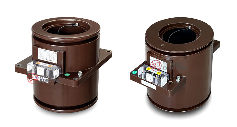
Product Display


The LMZB6-10Q / 160 has a compact cylindrical epoxy cast-resin body with a through-window opening and a square mounting base. The secondary terminal block is arranged on the side of the cast body, while the primary cable or busbar passes through the central aperture. This structure supports indoor switchgear installation where the CT is mounted around a busbar or cable path.
Applications
- 10kV, 11kV and 12kV class indoor medium-voltage switchgear
- XGN-10 fixed metal-enclosed switchgear and similar cabinet systems
- Incoming cabinets, outgoing feeder panels, and busbar metering circuits
- Current measurement and electric energy metering circuits
- Relay protection circuits using 5(10)P10 or 5(10)P20 protection cores
- High-current cable-through or busbar-through sensing in indoor distribution equipment
Features
- Fully enclosed epoxy resin structure: The resin-cast body provides insulation strength, mechanical stability, moisture resistance, and surface-cleaning capability for indoor use.
- Cable/busbar-through design: The primary conductor passes through the aperture, making the product suitable for high-current switchgear circuits without a wound primary coil.
- High-quality magnetic core: The core is made from high-quality magnetic material to support stable measurement and protection performance.
- Equipotential bus-window design: The bus fenestrae can be connected with equipotential lines during installation to support electric field control.
- Metering and protection cores: The product supports 0.2(S), 0.5(S), 5(10)P10, and 5(10)P20 configurations according to project requirements.
- Cabinet-ready installation: The cast-resin body includes four mounting holes and terminal marking for fixed switchgear installation.
Principle
The LMZB6-10Q / 160 current transformer operates according to electromagnetic induction. The primary cable or busbar passes through the central aperture and carries the primary current. The current produces magnetic flux in the internal magnetic core, and the secondary winding induces a proportional 5A or 1A current signal for meters, protection relays, or monitoring devices.
Because the product has no wound primary coil, it is especially suitable for high-current cable or busbar circuits. For metering applications, the selected 0.2(S) or 0.5(S) class must match the connected burden. For relay protection, the 5(10)P10 or 5(10)P20 protection core must be coordinated with the relay setting and fault-current level.
Model Designation

The model code LMZB6-10Q / 160 can be interpreted as follows:
| Code | Meaning |
|---|---|
| L | Current transformer |
| M | Busbar / cable-through structure |
| Z | Epoxy resin casting insulation |
| B | Protection-class configuration available |
| 6 | Design sequence code |
| 10 | Rated voltage class: 10kV |
| Q | Reinforced type |
| 160 | Aperture / inner-hole reference code |
Technical Data
| Item | Specification |
|---|---|
| Rated voltage class | 10kV class; suitable for 10kV, 11kV and 12kV class indoor systems by project confirmation |
| Rated insulation level | 12/42/75kV |
| Rated frequency | 50Hz / 60Hz |
| Rated secondary current | 5A or 1A |
| Rated primary current | 1000A–1500A, 2000A–3000A, 4000A–5000A |
| Accuracy classes | 0.2(S), 0.5(S), 5(10)P10, 5(10)P20 |
| Rated output | 15VA to 50VA depending on current range and accuracy class |
| Load power factor | cosφ = 0.8 lagging |
| Safety factor | FS < 10 where specified |
| Ambient temperature | -5°C to +40°C |
| Applicable standards | GB20840.2-2014, IEC61869-2:2012, and customer-specific requirements |
Selection Table
The selection table is organized by rated primary current range. Long table headers are wrapped into multiple lines for better responsive website display.
| Rated Primary Current (A) |
Class Combination |
0.2(S) Output (VA) |
0.5(S) Output (VA) |
5(10)P10 Output (VA) |
5(10)P20 Output (VA) |
|---|---|---|---|---|---|
| 1000–1500 | 0.2(S) / 0.2(S) 0.5(S) / 0.5(S) 0.2(S) / 5(10)P10 0.5(S) / 5(10)P10 0.2(S) / 5(10)P20 |
20 | 20 | 30 | 15 |
| 2000–3000 | 20 | 20 | 50 | 20 | |
| 4000–5000 | 30 | 30 | 50 | 30 |
Note: If project requirements exceed the listed range, final parameters may be determined by technical agreement between manufacturer and purchaser.
Dimensions
| Item | Catalogue Reference |
|---|---|
| Inner aperture reference | Ø160 / Ø162 reference according to drawing and model code |
| Outer body reference | Ø286 reference from drawing |
| Mounting plate width | 294mm reference |
| Mounting plate height | 350mm reference |
| Opening dimension | Ø290 reference with 260mm / 315mm mounting reference |
| Mounting holes | Four mounting holes shown in the outline drawing |
Terminals
The transformer uses subtractive polarity wiring. The incoming side of the busbar is marked as P1. The outlet terminals of the first secondary winding, used for 0.5 or 10P class depending on configuration, are marked as 1S1 / 1S2. The second protection secondary winding can be marked as 2S1 / 2S2.
| Terminal | Function | Application Note |
|---|---|---|
| P1 | Primary incoming side | Used to identify primary current direction and polarity. |
| 1S1 / 1S2 | First secondary winding | Used for metering or protection depending on ordered class. |
| 2S1 / 2S2 | Second secondary winding | Used for protection or additional secondary circuit where specified. |
| Equipotential connection | Bus-window electric screen | Connect to the bus equipotential line according to the installation requirement. |
Service Conditions
- Installation location: indoor medium-voltage switchgear
- Rated voltage: 10kV, 11kV and 12kV class systems by project confirmation
- Rated frequency: 50Hz / 60Hz
- Ambient temperature: -5°C to +40°C
- The installation environment should be free from severe vibration, corrosive gas, explosive medium, conductive dust, heavy pollution, and abnormal condensation.
- For high altitude, coastal, humid or heavy-pollution service conditions, technical confirmation is recommended before ordering.
Standards and Compliance
The LMZB6-10Q / 160 current transformer is designed according to GB20840.2-2014, IEC61869-2:2012, and customer-specific requirements. The product can be supplied with routine test documents according to the project agreement, including ratio test, polarity check, accuracy verification, insulation test, and power-frequency withstand test where required.
Installation and Dimensions

This product is suitable for fixed indoor switchgear such as XGN-10 type metal-enclosed cabinets and similar medium-voltage panel systems. Before cabinet production, the cable or busbar size, aperture clearance, mounting holes, terminal position, phase-to-ground clearance, equipotential connection, and secondary wiring access should be confirmed with the approved outline drawing.
Safety Notes
- Confirm primary current range, secondary current, accuracy class, rated output, and aperture size before production.
- Check that the cable, copper bar, or busbar can pass through the CT aperture with sufficient insulation clearance.
- Connect equipotential lines as required for the bus-window electric screen.
- The CT secondary circuit must not be open-circuited while primary current is flowing.
- Before disconnecting meters or relays, short-circuit the secondary circuit using an approved shorting device.
- One point of the secondary circuit should be grounded according to project electrical safety practice.
- Installation and commissioning shall be performed by qualified medium-voltage electrical personnel.
Ordering Info
- Product model: LMZB6-10Q / 160
- Rated primary current and rated secondary current: 5A or 1A
- Accuracy class combination and rated output for each secondary core
- Required protection class: 5(10)P10 or 5(10)P20
- Cable or busbar size and aperture requirement
- Mounting drawing, terminal direction, equipotential connection and switchgear layout
- Applicable standard, routine test report and certificate requirements
- Quantity, label language, packaging and project documentation requirements
Selection Guide
- Confirm voltage class: Use this product for indoor 10kV, 11kV and 12kV class switchgear after insulation coordination is confirmed.
- Select current range: Choose 1000A–1500A, 2000A–3000A or 4000A–5000A according to feeder load and busbar capacity.
- Select secondary current: Use 5A for conventional circuits or 1A where lower burden or longer secondary wiring is required.
- Define core duty: Use 0.2(S) or 0.5(S) for metering and 5(10)P10 or 5(10)P20 for protection.
- Verify output burden: Ensure connected meter, relay and wiring burden do not exceed the selected rated output.
- Check aperture and mounting: Confirm cable/busbar dimensions, mounting holes, and cabinet layout before production.
- Confirm terminal logic: Verify P1, 1S1/1S2, 2S1/2S2 and grounding/equipotential connection with the project wiring diagram.