Product Overview
The LZJC-12G / LZJC-12Q current transformer is an indoor single-phase epoxy cast-resin current transformer designed for 11kV and 12kV class medium-voltage switchgear. It is used for current measurement, electric energy metering, feeder monitoring, relay protection, and secondary-circuit isolation in indoor AC power systems. For international documentation, the product should be positioned as a 12kV class indoor cast-resin CT, suitable for common 11kV and 12kV switchgear projects under IEC-based technical requirements.
The LZJC-12G / LZJC-12Q series is based on the LZJC support-type cast-resin structure. The primary and secondary windings, together with the annular magnetic core, are fully encapsulated inside the epoxy resin body. The external groove design improves external insulation performance and supports reliable operation in humid and polluted indoor environments. Compared with larger support CTs or wall-through busbar CTs, this model is more suitable for compact switchgear where installation flexibility, mechanical strength, and clear terminal arrangement are required.
The product can be specified with 5A or 1A secondary current, with metering accuracy classes such as 0.2S, 0.2 and 0.5, and protection classes such as 10P10 and 10P15. The rated insulation level is 12/42/75kV, which is appropriate for IEC-oriented 12kV equipment-class documentation. For website structure and SEO, it is recommended to combine LZJC-12G and LZJC-12Q into one product family page, while distinguishing the two variants by installation structure, terminal arrangement, and project drawings.
Product Type
| Item | Specification |
|---|---|
| Product name | Indoor Single-Phase Epoxy Cast-Resin Current Transformer |
| Model series | LZJC-12G / LZJC-12Q |
| Structure | Fully enclosed support-type epoxy cast-resin CT with external insulation groove design |
| Voltage class | 11kV and 12kV class indoor medium-voltage systems |
| Rated insulation level | 12/42/75kV |
| Rated frequency | 50Hz; 60Hz available by project confirmation |
| Rated secondary current | 5A or 1A |
| Rated primary current | 5A to 1000A reference range according to variant and specification |
| Core configuration | Metering core, protection core, or combined metering/protection secondary groups |
| Typical application | Current measurement, energy metering, relay protection, feeder monitoring, SCADA signal input |
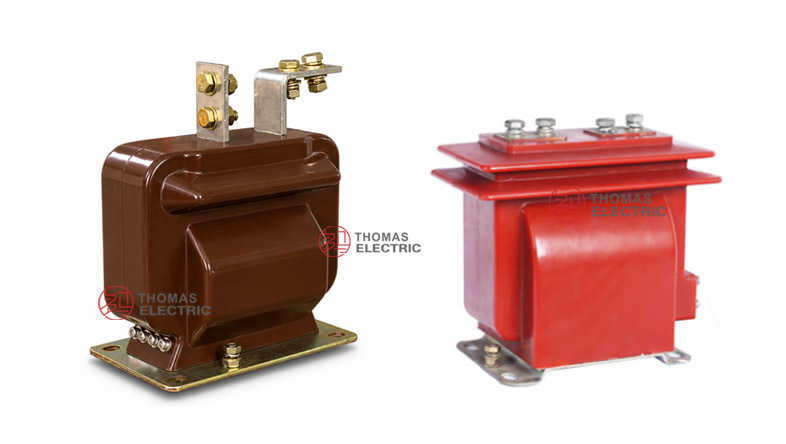
Product Display


The LZJC-12G / LZJC-12Q series adopts a compact support-type cast-resin body. Primary terminals are arranged on the upper side for busbar or bolted conductor connection, while secondary terminals are arranged on the lower or side terminal area according to the selected drawing. The external groove structure improves creepage performance and helps the CT maintain insulation reliability under indoor humidity, pollution, and compact switchgear conditions.
Applications
- 11kV and 12kV class indoor medium-voltage switchgear
- Fixed metal-enclosed switchgear, metering cabinets, feeder panels, and distribution switchboards
- Current measurement and energy metering circuits
- Relay protection circuits using 10P10 or 10P15 protection classes
- SCADA, feeder monitoring, power-quality monitoring, and automation signal circuits
- Compact switchgear projects requiring a fully enclosed support-type epoxy cast-resin CT
Features
- 12kV international voltage positioning: The product is written for 11kV and 12kV class IEC-oriented switchgear projects, with 12/42/75kV insulation level.
- Fully enclosed cast-resin body: The primary insulation, secondary windings, and magnetic core are sealed inside epoxy resin for stable indoor operation.
- External groove insulation design: The special groove structure improves external insulation distance and supports reliable operation in humid or polluted indoor environments.
- Flexible installation direction: Lightweight support-type construction allows installation in different orientations when cabinet clearance and mechanical fixing are confirmed.
- Metering and protection options: Accuracy classes can include 0.2S, 0.2, 0.5, 10P10 and 10P15 according to project requirements.
- 5A or 1A secondary output: 5A suits conventional metering and relay circuits, while 1A helps reduce burden for longer secondary wiring and digital protection systems.
Principle
The LZJC-12G / LZJC-12Q current transformer operates by electromagnetic induction. Primary current flows through the primary conductor path and generates magnetic flux in the annular magnetic core. The secondary winding then outputs a proportional current signal, normally 5A or 1A, to meters, protection relays, monitoring devices, or control systems.
The epoxy cast-resin insulation provides galvanic isolation between the medium-voltage primary circuit and low-voltage secondary circuit. For metering duty, the CT must maintain ratio and phase accuracy within the rated burden. For protection duty, the protection core must deliver reliable output under fault-current conditions. Therefore, current ratio, burden, secondary current, accuracy class, terminal grouping, and short-circuit withstand ratings should be selected together during engineering confirmation.
Model Designation
| Code | Meaning |
|---|---|
| L | Current transformer |
| Z | Indoor support / pillar type structure |
| J | Reinforced design or enhanced structural reference |
| C | Cast-resin insulated, fully enclosed structure |
| 12 | 12kV voltage class for 11kV and 12kV class indoor systems |
| G | Structural / installation variant code; final meaning follows factory drawing |
| Q | Reinforced / installation variant code; final meaning follows factory drawing |
Technical Data
| Item | Specification |
|---|---|
| Rated voltage class | 11kV and 12kV class indoor systems |
| Rated insulation level | 12/42/75kV |
| Rated frequency | 50Hz; 60Hz by agreement |
| Rated secondary current | 5A or 1A |
| Rated primary current | 5A to 1000A reference range; custom ratios by technical agreement |
| Accuracy classes | Metering: 0.2S, 0.2, 0.5; Protection: 10P10, 10P15 |
| Rated burden | 10VA, 15VA, 20VA or project-specific rated output per secondary core |
| Burden power factor | cosφ = 0.8 lagging unless otherwise specified |
| Short-circuit withstand | Ith and Idyn according to current ratio, nameplate and factory test report |
| Ambient temperature | -5°C to +55°C; special conditions by agreement |
| Applicable standards | IEC 61869-1, IEC 61869-2, GB/T 20840.1, GB/T 20840.2; legacy IEC 60044-1 / GB1208 references by project agreement |
Selection Table
The following table is organized for preliminary product selection. Final values shall follow the approved drawing, nameplate, and factory test report.
| Rated
Primary Current (A) |
Accuracy
Class Combination |
Rated
Output(VA) |
Short-Time
Thermal Current |
Dynamic
Current |
|---|---|---|---|---|
| 5–100 | 0.2S / 10P10 0.2 / 10P15 0.5 / 10P10 |
10 / 15 10 / 15 10 / 20 |
100 × In | 250 × In |
| 150 | 0.2S / 10P10 | 15 / 15 | 13.5kA | 34kA |
| 200 | 0.2 / 10P15 | 15 / 15 | 18kA | 45kA |
| 300 | 0.5 / 10P10 | 15 / 20 | 27kA | 67.5kA |
| 400 | 0.2S / 10P15 | 15 / 15 | 36kA | 90kA |
| 500 | 0.2 / 10P10 | 20 / 20 | 45kA | 112.5kA |
| 600 | 0.5 / 10P15 | 15 / 20 | 54kA | 135kA |
| 750 | 0.2S / 10P10 | 20 / 20 | 63kA | 130kA |
| 800–1000 | 0.5 / 10P15 | 20 / 20 | 63kA | 130kA |
Note: Accuracy class combination indicates the available metering/protection secondary configuration. Rated output is specified per secondary core. Ith may be expressed as kA or as multiples of rated primary current depending on project specification.
G / Q Variant Selection
| Variant | Recommended Use | Engineering Note |
|---|---|---|
| LZJC-12G | General indoor support-type cast-resin CT applications | Recommended when the project drawing or cabinet layout matches the G-type installation structure. |
| LZJC-12Q | Reinforced / alternative installation variant | Recommended when the switchgear requires the Q-type mounting or terminal arrangement. |
| Combined G/Q page | Website SEO and product family organization | Use one product page for both variants, while final selection follows the approved drawing and nameplate. |
Dimensions
Outline dimensions and fixing details shall be confirmed by the selected LZJC-12G or LZJC-12Q drawing. Because the two variants may differ in mounting holes, primary terminal arrangement, and secondary terminal direction, the switchgear layout should be checked before production.
| Item | Engineering Note |
|---|---|
| Mounting structure | Support-type base for indoor switchgear installation; mounting holes follow approved drawing. |
| Primary terminals | Top-mounted P1 / P2 busbar terminals with polarity marking. |
| Secondary terminals | Terminal groups for metering and protection circuits according to the ordered configuration. |
| External insulation | Groove design improves external insulation performance and creepage reliability. |
| Installation orientation | Flexible installation direction, subject to mechanical fixing, clearance and terminal access. |
Windings & Terminal Marking

The LZJC-12G / LZJC-12Q current transformer follows standard CT polarity marking. The reference primary current direction is from P1 to P2. Secondary terminal marking depends on the number and function of secondary windings.
| Terminal | Function | Application Note |
|---|---|---|
| P1 / P2 | Primary terminals | Top-mounted primary busbar terminals with polarity reference. |
| 1S1 / 1S2 | First secondary winding | Commonly used for metering or measurement applications. |
| 2S1 / 2S2 | Second secondary winding | Commonly used for relay protection applications, where applicable. |
| 3S1 / 3S2 | Additional secondary winding | Used only when an additional protection or monitoring core is specified. |
| Grounding point | Secondary grounding reference | One point of the secondary circuit should be grounded according to project electrical practice. |
Correct terminal identification is essential for metering accuracy, relay direction, and protection stability. Secondary terminals must never be left open when the primary circuit is energized.
Service Conditions
- Installation location: indoor medium-voltage switchgear
- Rated voltage: 11kV and 12kV class systems
- Rated frequency: 50Hz; 60Hz by agreement
- Altitude: not exceeding 1000m under standard service conditions unless otherwise specified
- Ambient temperature: -5°C to +55°C; special temperature range by technical agreement
- Relative humidity and pollution level should comply with IEC instrument transformer service conditions and project specification.
- Installation environment should be free from severe vibration, explosive medium, conductive dust, corrosive gas and abnormal condensation.
Standards and Compliance
For international product pages, the LZJC-12G / LZJC-12Q current transformer should be specified according to IEC 61869-1 and IEC 61869-2. Where GB documentation is required, GB/T 20840.1 and GB/T 20840.2 can be used. Older references such as IEC 60044-1 and GB1208-2006 may be retained only as legacy catalogue references when required by the customer or tender document.
Installation and Dimensions

The transformer shall be securely mounted using the designated fixing holes. Primary conductor connection may be made by busbar or bolted terminals depending on the selected variant. Adequate clearance must be maintained for insulation, heat dissipation, terminal access, and maintenance. Before switchgear production, confirm primary terminal spacing, secondary wiring direction, base mounting holes, phase-to-ground distance, and final installation orientation.
Safety Notes
- Confirm voltage class, insulation level, current ratio, secondary current, accuracy class and rated burden before production.
- Check primary terminal spacing, mounting holes, secondary terminal access and grounding position before switchgear assembly.
- Connect primary and secondary terminals according to polarity marks and approved wiring diagram.
- The CT secondary circuit must not be open-circuited while primary current is flowing.
- Before disconnecting meters or relays, short-circuit the secondary circuit with an approved shorting device.
- One point of the secondary circuit should be reliably grounded according to local electrical safety regulations.
- Installation and commissioning shall be performed by qualified medium-voltage electrical personnel.
Ordering Info
- Product model: LZJC-12G or LZJC-12Q
- Voltage class: 11kV or 12kV class
- Rated primary current and transformation ratio
- Rated secondary current: 5A or 1A
- Accuracy class combination: metering, measurement, protection, or combined metering/protection
- Rated burden for each secondary winding
- Short-circuit withstand requirements: Ith and Idyn
- Terminal grouping and winding allocation: 1S / 2S / 3S where applicable
- Mounting drawing, primary terminal type, cabinet layout and installation orientation
- IEC standard requirement, routine test report, certificate, label language and packaging requirement
Selection Guide
- Use the correct voltage wording: For international pages, use 11kV and 12kV class, with 12/42/75kV insulation level.
- Select G or Q variant: Choose LZJC-12G or LZJC-12Q according to the cabinet drawing, mounting holes and terminal arrangement.
- Choose current ratio: Select the rated primary current according to feeder load, metering range and protection settings.
- Select secondary current: Use 5A for conventional systems or 1A where lower burden and longer secondary wiring are required.
- Define accuracy class: Use 0.2S / 0.2 / 0.5 for metering and 10P10 / 10P15 for protection circuits.
- Verify burden and short-circuit ratings: Check rated burden, Ith and Idyn against the meter, relay, secondary cable and switchgear fault level.
- Approve drawings: Confirm outline dimensions, terminal marking, mounting base and clearance before production.