Product Overview
The LZZ-10 (AK12) current transformer is an indoor single-phase epoxy cast-resin current transformer designed for 11kV and 12kV class medium-voltage switchgear. It is used for current measurement, electric energy metering, feeder monitoring and relay protection in AC power systems with rated frequency of 50Hz or 60Hz. For international product documentation, this model is best positioned as a 12kV class indoor post-type cast-resin CT, suitable for 10kV, 11kV and 12kV indoor switchgear projects after insulation coordination is confirmed.
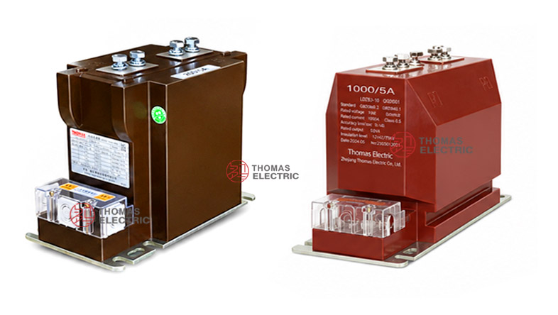
The product adopts a fully enclosed post-type epoxy resin casting structure. The primary winding, secondary winding and magnetic core are integrated into the resin-cast body, while the primary terminals P1 / P2 are led out from the top of the product. The secondary terminals are arranged at the lower side terminal box, supporting clear wiring access for measurement and protection circuits. This structure provides stable insulation performance, compact installation and reliable mechanical strength for indoor medium-voltage distribution equipment.
The LZZ-10 (AK12) platform is different from wall-through or window-type CTs. It is more suitable for switchgear panels requiring a compact support/post-type current transformer with top primary terminals, lower secondary terminals and a fully enclosed cast-resin body. The rated insulation level is 12/42/75kV, which allows the product to be described in IEC-oriented documentation as a 12kV equipment-class CT for 11kV and 12kV systems. Typical accuracy classes include 0.2, 0.5 and 10P10, with 5A or 1A secondary output available by project specification.
Product Type
| Item | Specification |
|---|---|
| Product name | Indoor Post-Type Epoxy Cast-Resin Current Transformer |
| Model series | LZZ-10 (AK12) |
| Structure | Fully enclosed support/post-type epoxy resin cast structure |
| Voltage class | 10kV, 11kV and 12kV class indoor medium-voltage systems |
| Rated insulation level | 12/42/75kV |
| Rated frequency | 50Hz or 60Hz |
| Rated secondary current | 5A or 1A |
| Typical rated primary current | 50A to 630A reference range according to supplied catalogue data |
| Typical application | Energy metering, current measurement, relay protection, feeder monitoring |
Product Display
 Post-Type Epoxy Cast-Resin Current Transformer Thomas Electric")
 Post-Type Epoxy Cast-Resin Current Transformer Thomas Electric")
The LZZ-10 (AK12) current transformer has a compact rectangular cast-resin body with four top primary terminal bolts and a lower-side secondary terminal box. The base plate provides fixed mounting inside indoor switchgear. The wiring diagram supports both a simple two-terminal secondary winding arrangement and a multi-tap secondary terminal arrangement, depending on the ordered configuration.
Applications
- 10kV, 11kV and 12kV class indoor medium-voltage switchgear
- Fixed metal-enclosed switchgear, metering cabinets and feeder panels
- Current measurement and electric energy metering circuits
- Relay protection circuits using 10P10 protection class
- Distribution substations, industrial power rooms and utility feeder cabinets
- OEM switchgear projects requiring compact post-type cast-resin CT installation
Features
- Post-type cast-resin structure: The primary winding, secondary winding and core are enclosed in one epoxy resin body for stable insulation and mechanical protection.
- International 12kV class positioning: The 12/42/75kV insulation level supports 11kV and 12kV class IEC-oriented project documentation.
- Compact switchgear installation: The top primary terminals and lower secondary terminal box allow practical installation in standard indoor panels.
- Metering and protection use: Accuracy classes such as 0.2, 0.5 and 10P10 support current measurement, energy metering and relay protection.
- 5A or 1A secondary output: 5A is suitable for conventional meter and relay systems; 1A can be selected where lower burden or longer secondary wiring is required.
- Suitable for microprocessor-based devices: For digital meters and microprocessor relays, 0.2 and 0.5 class secondary burden can be specified down to low VA values when confirmed by technical agreement.
Principle
The LZZ-10 (AK12) current transformer operates by electromagnetic induction. The primary winding carries the medium-voltage circuit current and generates magnetic flux in the core. The secondary winding then delivers a proportional low-current signal, normally 5A or 1A, to meters, energy metering devices, protection relays or monitoring systems.
For measurement and metering duty, the transformer must maintain ratio accuracy and phase displacement within the rated burden. For protection duty, the protection winding must provide a dependable current signal during fault-current conditions. Current ratio, secondary current, burden, accuracy class, short-time thermal current and dynamic current should be confirmed together with the switchgear and relay protection design.
Model Designation
| Code | Meaning |
|---|---|
| L | Current transformer |
| Z | Cast-resin insulated / indoor structure reference |
| Z | Post-type / support-type structural series reference |
| 10 | Catalogue voltage-class reference; internationally documented as 11kV / 12kV class by insulation confirmation |
| AK12 | Manufacturer structural designation for the compact post-type version |
Technical Data
| Item | Specification |
|---|---|
| Rated voltage class | 10kV, 11kV and 12kV class indoor systems by project confirmation |
| Rated insulation level | 12/42/75kV |
| Rated frequency | 50Hz or 60Hz |
| Rated secondary current | 5A or 1A |
| Rated primary current | 50A, 75A, 100A, 150A, 200A, 300A, 400A, 500A, 600A, 630A reference values |
| Accuracy classes | 0.2, 0.5, 10P10 |
| Rated output | 0.2 class: 10VA; 0.5 class: 15VA; 10P10 class: 10VA reference |
| Rated short-time thermal current | 7.5kA to 40kA reference range depending on primary current |
| Rated dynamic current | 19kA to 100kA reference range depending on primary current |
| Load power factor | cosφ = 0.8 lagging unless otherwise specified |
| Ambient temperature | -5°C to +55°C reference range; project-specific conditions by agreement |
| Applicable standards | IEC 61869-1, IEC 61869-2, GB/T 20840.1, GB/T 20840.2; legacy IEC 60044-1 / GB1208 references by project agreement |
Selection Table
The following table is reorganized from the supplied catalogue data and adapted for website display. Long headers are split into multiple lines to keep the table readable on product pages.
| Primary
Current (A) |
Accuracy
Class Combination |
Rated
Output (VA) |
Short-Time
Thermal Current Ith (kA) |
Dynamic
Current Idyn (kA) |
|---|---|---|---|---|
| 50 | 0.2 0.5 10P10 |
0.2: 10 0.5: 15 10P10: 10 |
7.5 | 19 |
| 75 | 11.25 | 28 | ||
| 100 | 15 | 37.5 | ||
| 150 | 22.5 | 56 | ||
| 200 | 30 | 75 | ||
| 300 | 40 | 100 | ||
| 400 | ||||
| 500 | ||||
| 600 | ||||
| 630 |
Note: The table is for preliminary selection. Final current ratio, rated burden, accuracy class, thermal current, dynamic current, terminal arrangement, insulation test and routine test requirements shall be confirmed according to the nameplate, approved drawing and factory test report.
Dimensions
| Item | Catalogue Reference | Engineering Note |
|---|---|---|
| Overall length | Approx. 255mm reference | Used for cabinet depth and mounting layout check. |
| Overall height | Approx. 187–190mm reference | Confirm vertical clearance before switchgear assembly. |
| Overall width | Approx. 148–150mm reference | Check side clearance and secondary terminal access. |
| Base mounting | Base plate with elongated mounting holes | Mounting hole position must follow the approved drawing. |
| Primary terminals | Top P1 / P2 terminal arrangement | Confirm busbar or cable lug connection and phase clearance. |
| Secondary terminals | Lower side terminal box | Confirm terminal direction, wiring path and grounding point. |
Windings & Terminal Marking
The LZZ-10 (AK12) uses standard current transformer polarity marking. The primary winding terminals are marked P1 and P2 and are led out from the top of the product. The secondary terminals are arranged at the lower side of the resin body and may be supplied in different forms according to the ordered configuration.
| Terminal | Function | Application Note |
|---|---|---|
| P1 / P2 | Primary terminals | Top-mounted primary terminals used for primary current direction and polarity reference. |
| S1 / S2 | Standard secondary winding | Used for a single measurement, metering or protection secondary circuit. |
| S1 / S2 / S3 | Secondary tap arrangement | Used when a tapped secondary winding or special wiring diagram is specified. |
| Grounding point | Secondary grounding reference | One point of the secondary circuit should be grounded according to project electrical safety practice. |
Correct terminal identification is essential for metering accuracy and protection direction. The secondary circuit must not be left open when primary current is flowing.
 Post-Type Epoxy Cast-Resin Current Transformer Thomas Electric")
Service Conditions
- Installation location: indoor medium-voltage switchgear
- Rated voltage: 10kV, 11kV and 12kV class systems by project confirmation
- Rated frequency: 50Hz or 60Hz
- Ambient temperature: -5°C to +55°C reference range unless otherwise specified
- Indoor environment should be free from conductive dust, corrosive gas, explosive medium, heavy pollution and abnormal condensation.
- For high humidity, coastal, high altitude or heavy-pollution projects, insulation distance and creepage coordination should be confirmed before ordering.
Standards and Compliance
For new international projects, the LZZ-10 (AK12) current transformer should be specified according to IEC 61869-1 and IEC 61869-2 for instrument transformers and current transformers. Where GB documentation is required, GB/T 20840.1 and GB/T 20840.2 can be used. Legacy references such as IEC 60044-1, IEC 185, GB1208-1997 and GB1208-2006 may be retained only when required by customer documentation or tender specifications.
Installation and Dimensions
 Post-Type Epoxy Cast-Resin Current Transformer Thomas Electric")
The product should be installed securely inside indoor switchgear using the designated base mounting holes. Before cabinet production, the top primary terminal spacing, busbar or cable-lug connection, base hole position, lower secondary terminal direction, grounding point, and maintenance space should be confirmed with the approved outline drawing. Because the product is a compact post-type CT, cabinet clearance and terminal access should be checked carefully before assembly.
Safety Notes
- Confirm voltage class, insulation level, current ratio, secondary current, accuracy class and rated burden before production.
- Check primary terminal spacing, busbar clearance, mounting holes, secondary terminal access and grounding position before switchgear assembly.
- Connect primary and secondary terminals according to polarity marks and the approved wiring diagram.
- The CT secondary circuit must not be open-circuited while primary current is flowing.
- Before disconnecting meters or relays, short-circuit the secondary circuit with an approved shorting device.
- One point of the secondary circuit should be reliably grounded according to local electrical safety regulations.
- Installation and commissioning shall be performed by qualified medium-voltage electrical personnel.
Ordering Info
- Product model: LZZ-10 (AK12)
- Voltage class: 10kV, 11kV or 12kV class
- Rated primary current and transformation ratio
- Rated secondary current: 5A or 1A
- Accuracy class: 0.2, 0.5 or 10P10
- Rated burden / output for each secondary circuit
- Rated short-time thermal current and rated dynamic current
- Terminal arrangement: S1/S2 or S1/S2/S3 if required
- Mounting drawing, primary terminal type, cabinet layout and wiring diagram
- IEC standard requirement, routine test report, certificate, label language and packaging requirement
Selection Guide
- Confirm voltage class: Use 11kV and 12kV class wording for international pages, with 12/42/75kV insulation level.
- Select current ratio: Choose the rated primary current according to feeder load, metering range and protection settings.
- Select secondary current: Use 5A for conventional systems or 1A where lower burden and longer secondary wiring are required.
- Define circuit function: Use 0.2 or 0.5 for metering and measurement, and 10P10 for relay protection.
- Check burden: Confirm meter, relay, terminal and cable burden. Low-burden digital devices may require lower VA confirmation.
- Verify short-circuit ratings: Check Ith and Idyn against the switchgear fault level.
- Approve drawings: Confirm outline dimensions, mounting base, P1/P2 terminals and secondary terminal marking before production.