Product Overview
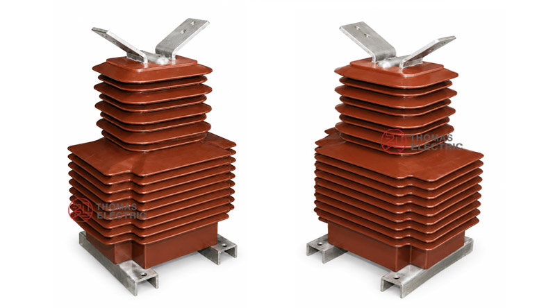
The LZZB8-35W / LZZBW8-35 / LZZBJ71-35W GY outdoor cast-resin current transformer is a 35kV-class outdoor high-voltage current transformer designed for current measurement, energy metering and relay protection in medium- and high-voltage distribution systems. For international projects, this product family should be described according to the 35kV / 40.5kV equipment class, with insulation levels such as 40.5/95/185kV or project-specific impulse withstand ratings according to IEC requirements.
This series is positioned as a 35kV outdoor epoxy resin cast CT with high creepage distance and strong pollution resistance. Compared with oil-immersed iron-tank CTs, it is dry-type, oil-free and easier to maintain. Compared with compact 24kV outdoor epoxy CTs, it is designed for a higher voltage platform, larger insulation distance, higher outdoor creepage requirement and more demanding environmental conditions.
Product Type


| Item | Specification |
|---|---|
| Product name | Outdoor Epoxy Resin Cast Current Transformer |
| Model range | LZZB8-35W / LZZBW8-35 / LZZBJ71-35W GY |
| Installation condition | Outdoor |
| Structure | Fully enclosed post-type / pillar-type epoxy resin cast structure |
| Insulation medium | Outdoor-grade epoxy resin, dry-type insulation |
| Application | Current measurement, energy metering and relay protection |
| International voltage class | 35kV / 40.5kV class high-voltage power system |
| Rated insulation level | 40.5/95/185kV reference; 40.5/95/190kV available by project specification |
| Rated secondary current | 5A or 1A |
| Outdoor insulation feature | Creepage distance greater than 1200mm for high-pollution-resistant versions |
Model Explanation

- L: Current transformer.
- Z: Post-type / pillar-type structure.
- Z: Cast-resin insulation.
- B: With protection winding / metering and protection current transformer series.
- 8 / 71: Design sequence or manufacturer structure code.
- 35: 35kV rated voltage class, normally matched with 40.5kV highest system voltage.
- W: Outdoor installation.
- GY: Outdoor high-voltage / high-pollution-resistant structure code used by some manufacturers.
- 5A or 1A: Rated secondary current option.
- Accuracy class: Metering classes such as 0.2, 0.2S, 0.5, 0.5S and protection classes such as 5P or 10P according to project requirements.
Applications
- 35kV / 40.5kV outdoor substations and feeder bays
- Outdoor current measurement and energy metering points
- Relay protection for feeders, transformers and capacitor banks
- Industrial and mining enterprise 35kV power distribution systems
- Renewable energy substations for solar, wind and energy storage projects
- Outdoor grid connection points requiring oil-free instrument transformers
- Humid, polluted or coastal environments requiring increased creepage distance
Features
- Outdoor dry-type insulation: Fully enclosed epoxy resin casting eliminates transformer oil and reduces leakage-related maintenance concerns.
- 35kV international voltage platform: Written as 35kV / 40.5kV class for IEC-style projects and international tender documents.
- High creepage design: Surface creepage distance can be greater than 1200mm for high resistance to dirt, humidity and tracking.
- High accuracy: Metering classes such as 0.2, 0.2S, 0.5 and 0.5S support billing, measurement and monitoring applications.
- Protection stability: 5P and 10P protection classes support relay protection, short-circuit detection and grid fault management.
- High dynamic thermal withstand: Designed to maintain electrical and mechanical stability under short-time fault-current conditions.
- Flexible mounting: Post-type fully enclosed structure is compact, moisture-resistant and can be installed according to outdoor layout requirements.
Operating Principle
The LZZB8-35W / LZZBW8-35 / LZZBJ71-35W GY current transformer converts the high primary current of a 35kV circuit into a standardized secondary current, normally 5A or 1A. The secondary output is supplied to meters, relays or monitoring equipment. The cast-resin insulation body provides electrical isolation between the high-voltage primary circuit and the low-voltage secondary circuits.
For metering, the CT must maintain ratio accuracy and phase displacement within the selected accuracy class and rated burden. For protection, the protection winding must reproduce fault-current signals within the required accuracy limit. Therefore, current ratio, secondary current, accuracy class, rated output, short-time thermal current and dynamic current should be selected together.
Technical Data
| Parameter | Specification |
|---|---|
| Model range | LZZB8-35W / LZZBW8-35 / LZZBJ71-35W GY |
| Product type | Outdoor epoxy resin cast current transformer |
| Rated voltage class | 35kV / 40.5kV |
| Rated insulation level | 40.5/95/185kV reference; 40.5/95/190kV by project requirement |
| Rated frequency | 50Hz or 60Hz |
| Rated primary current | 15A to 2000A reference range |
| Rated secondary current | 5A or 1A |
| Accuracy class | 0.2, 0.2S, 0.5, 0.5S, 5P, 10P |
| Rated output | 10VA, 20VA or 50VA reference; project-specific burden available |
| Power factor | cosφ = 0.8 lag reference |
| Number of secondary windings | 1 to 5 depending on project configuration |
| Creepage distance | Greater than 1200mm for high-pollution-resistant versions |
| Operating temperature | -40°C to +40°C reference; other ranges by agreement |
| Altitude | ≤ 3000m reference according to supplied information; higher altitude by project confirmation |
| Pollution class | Class IV reference for some versions; class 3 or 4 by project requirement |
| Approximate maximum dimensions | 435 × 610 × 330mm reference from related technical information |
| Applicable standards | IEC 61869-1, IEC 61869-2, GB/T 20840.1, GB/T 20840.2; legacy IEC 185 / GB1208 references by agreement |
Selection Table
The following table is reorganized from the supplied data and optimized for website display. Long headings and repeated values are simplified to avoid broken table layout.
| Model | Rated Primary Current (A) |
Accuracy Class Combination |
Rated Output (VA) |
Rated Short-Time Thermal Current |
Rated Dynamic Current |
|---|---|---|---|---|---|
| LZZB8-35W | 15 | 0.2 / 10P10 0.5 / 10P10 |
0.2: 10VA 0.5: 20VA 10P10: 50VA |
2.25kA / 2s | 5.6kA |
| 20 | 3.0kA / 2s | 7.5kA | |||
| 30 | 4.5kA / 2s | 11.25kA | |||
| 40 | 6.0kA / 2s | 15kA | |||
| 50 | 7.5kA / 2s | 18.75kA | |||
| 75 | 0.2: 10VA 0.5: 20VA 10P10: 50VA |
11.25kA / 2s | 28kA | ||
| 100 | 15kA / 2s | 37.5kA | |||
| 150 | 31.5kA / 1s | 80kA | |||
| LZZB8-35W | 200 | 0.2 / 10P10 0.5 / 10P10 |
0.2: 10VA 0.5: 20VA 10P10: 50VA |
31.5kA / 2s | 80kA |
| 300 | 31.5kA / 3s | 80kA | |||
| 400 | 0.2: 15VA 0.5: 30VA 10P10: 50VA |
31.5kA / 3s | 80kA | ||
| 500 | 31.5kA / 3s | 80kA | |||
| 600 | 0.2: 15VA 0.5: 30VA 10P10: 50VA |
31.5kA / 4s | 80kA | ||
| 800 | 0.2: 50VA 0.5: 50VA 10P10: 50VA |
31.5kA / 4s | 80kA | ||
| 1000–2000 | 40kA / 4s | 100kA |
Note: The table is for preliminary selection. Final current ratio, rated output, accuracy class, secondary winding quantity, short-time thermal current and dynamic current shall be confirmed according to the nameplate, approved drawing and factory test report.
Normal Operating Conditions
| Parameter | Value |
|---|---|
| Installation place | Outdoor |
| Ambient temperature | -40°C to +40°C reference |
| Altitude | ≤ 3000m reference; altitude correction by project requirement |
| Pollution level | Class 3 / Class 4 or Class IV reference depending on project requirement |
| Atmospheric condition | Suitable for outdoor moisture, dirt and tracking-resistant insulation applications |
| Installation condition | No severe shock, abnormal vibration or mechanical load beyond approved design limits |
Installation and Dimensions

The product should be installed vertically on a stable outdoor foundation, steel structure, pole-mounted support or substation bracket. Before installation, confirm the base mounting holes, primary terminal direction, conductor angle, grounding point, secondary terminal box and required electrical clearance.
| Dimension / Installation Item | Reference Value / Recommended Check Point |
|---|---|
| Overall height | Approx. 602mm reference from supplied drawing |
| Top terminal direction | 45° direction reference shown in drawing |
| Front base width | Approx. 240 ± 0.5mm reference |
| Side body width | Approx. 275 ± 0.5mm / 295mm reference |
| Maximum outline reference | 435 × 610 × 330mm reference from related technical information |
| Terminal plates | Different terminal plate dimensions for 5–750/5 and 800–2000/5 current ranges |
| Mounting holes | Four mounting holes, Ø13 reference from supplied drawing |
| Installation check | Confirm bracket strength, electrical clearance, grounding and cable outlet before energizing. |
Windings & Terminal Marking
The product can be configured with one or multiple secondary windings. Typical terminal markings follow metering and protection circuit functions. The final terminal arrangement must follow the approved wiring diagram and nameplate.
| Terminal Marking | Function | Application Note |
|---|---|---|
| P1 / P2 | Primary terminals | Used for primary current direction and polarity reference. |
| S1 / S2 | Single secondary winding | Used for one metering or protection output. |
| 1S1 / 1S2 | First secondary winding | Usually assigned to metering or current measurement. |
| 2S1 / 2S2 | Second secondary winding | Usually assigned to relay protection. |
| 3S1 / 3S2 | Additional winding when specified | Used for independent monitoring, backup protection or separate metering circuit. |
| Grounding point | Secondary / base grounding | One point of the secondary circuit and the transformer base should be grounded according to project practice. |
Standards and Compliance
For new international documentation, this 35kV outdoor cast-resin current transformer family should be specified according to IEC 61869-1 and IEC 61869-2. For Chinese standard documentation, GB/T 20840.1 and GB/T 20840.2 can be used. Older catalogues may mention IEC 185, GB1208 or GB1208-1997; these can be kept only as legacy references when required by tenders or customer comparison documents.
Safety Notes
- Confirm voltage class, insulation level, current ratio, secondary current, accuracy class and rated burden before installation.
- Check P1 / P2 polarity and secondary terminal marking before connecting meters or protection relays.
- Confirm outdoor electrical clearance, creepage distance, mounting strength and conductor mechanical load before energizing.
- Ground the transformer base and one point of the secondary circuit according to the substation grounding design.
- The CT secondary circuit must not be open-circuited while primary current is flowing.
- Before disconnecting meters, relays or test equipment, short-circuit the secondary circuit with an approved shorting device.
- Seal the secondary terminal box after wiring to reduce moisture ingress and maintain outdoor reliability.
- Installation and commissioning shall be performed by qualified high-voltage electrical personnel.
Selection Guide
- Confirm voltage platform: Use 35kV / 40.5kV for international IEC-style product pages and tenders.
- Confirm insulation level: Use 40.5/95/185kV as the standard reference; use 40.5/95/190kV when specified by the project.
- Choose the structure code: Use LZZB8-35W for general outdoor resin casting type, LZZBW8-35 for outdoor high-voltage cast-resin type, and LZZBJ71-35W GY when emphasizing high creepage and outdoor pollution resistance.
- Select current ratio: Match the primary current to feeder load, metering range and relay protection setting.
- Define accuracy combination: Use 0.2 / 0.2S for higher metering accuracy, 0.5 / 0.5S for general measurement, and 5P / 10P for protection.
- Check creepage requirement: For polluted or humid regions, specify creepage distance greater than 1200mm or confirm according to pollution class.
- Approve drawings: Confirm outline dimensions, primary terminal angle, mounting holes, terminal box arrangement and wiring diagram before production.