Product Overview
The LZZBJ9-10B / LZZBJ9-12B current transformer is an indoor epoxy resin cast, fully enclosed, post-type current transformer designed for medium-voltage AC power systems. It is suitable for 10kV, 11kV, and 12kV switchgear applications and is used for current measurement, electric energy metering, feeder monitoring, and relay protection in power systems with rated frequency of 50Hz or 60Hz.
The B-type series uses electrical-grade epoxy resin casting to enclose the primary winding, secondary winding, and magnetic core into a compact insulated body. The structure provides insulation strength, moisture resistance, electrical performance, and mechanical support for indoor switchgear installation. The product is supplied with primary lead-out boards for wiring and bottom mounting inserts for cabinet installation.
Product Type
| Item | Specification |
|---|---|
| Product name | Indoor Epoxy Resin Cast Fully Enclosed Current Transformer |
| Model series | LZZBJ9-10B / LZZBJ9-12B |
| Product structure | Indoor, single-phase, epoxy resin cast, fully enclosed, post-type current transformer |
| Voltage class | 10kV, 11kV, and 12kV medium-voltage systems |
| Rated frequency | 50Hz / 60Hz |
| Rated secondary current | 5A or 1A according to project requirement |
| Core configuration | Metering core, protection core, or combined metering/protection core configuration |
| Installation location | Indoor medium-voltage switchgear and distribution equipment |
| Typical applications | Current measurement, energy metering, relay protection, feeder monitoring, switchgear instrumentation |
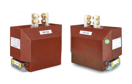
Product Display


Main Applications
- 10kV, 11kV, and 12kV indoor medium-voltage distribution systems
- Metal-clad switchgear, feeder cabinets, circuit breaker panels, and distribution rooms
- Current measurement and electric energy metering circuits
- Relay protection systems for feeders, transformers, motors, and distribution lines
- SCADA, power monitoring, and energy management systems
- Switchgear assemblies requiring compact post-type CT installation and primary board connection
Key Technical Features
- Fully enclosed epoxy resin casting: The primary winding, secondary winding, and core are molded into an insulated body for stable indoor medium-voltage operation.
- B-type post structure: The B-type mechanical layout is suitable for switchgear requiring primary lead-out boards and bottom mounting inserts.
- Compact and lightweight design: The cast-resin body supports easier installation, cleaning, and maintenance inside cabinet systems.
- Metering and protection combinations: Accuracy combinations can include 0.2S, 0.5S, 0.2, 0.5 and protection classes such as 10P10, 10P15 or 10P20 according to order requirements.
- 1A or 5A secondary output: Compatible with medium-voltage meters, protection relays, monitoring units, and switchgear secondary systems.
- Short-circuit withstand selection: Short-time thermal current and dynamic current ratings are selected according to current ratio and system fault level.
Working Principle
The LZZBJ9-10B / LZZBJ9-12B current transformer operates according to electromagnetic induction. When current flows through the primary circuit, magnetic flux is generated in the core, and the secondary winding outputs a proportional current signal for meters, relays, or monitoring devices. The epoxy resin insulation system separates the medium-voltage primary circuit from the low-voltage secondary circuit and supports safe signal transmission under rated service conditions.
For metering applications, the CT should maintain the specified ratio accuracy and phase displacement within the rated burden. For relay protection applications, the protection core should provide a reliable signal under fault-current conditions and coordinate with the relay pickup setting and accuracy limit factor.
Model Designation

The model code can be interpreted as follows:
| Code | Meaning |
|---|---|
| L | Current transformer |
| Z | Indoor type |
| Z | Cast-resin insulated / fully enclosed structure |
| B | Protection configuration available for metering and relay protection applications |
| J | Reinforced design / enhanced insulation structure |
| 9 | Design sequence / product platform |
| 10 / 12 | Voltage class identification for 10kV, 11kV, or 12kV project applications |
| B | B-type mechanical structure with primary lead-out board and bottom mounting inserts |
Technical Data
| Item | Specification |
|---|---|
| Rated voltage class | 10kV / 11kV / 12kV medium-voltage systems |
| Rated frequency | 50Hz / 60Hz |
| Installation site | Indoor |
| Rated primary current | 10A to 2500A reference range; other ratios subject to project confirmation |
| Rated secondary current | 5A or 1A |
| Accuracy class combination | 0.2S / 10P10, 0.5S / 10P10, 0.2 / 10P10, 0.5 / 10P10, 0.2 / 10P20, 0.5 / 10P20 and other project combinations |
| Rated output | 10VA / 15VA / 20VA according to measuring and protection core configuration |
| Insulation structure | Electrical-grade epoxy resin casting, fully enclosed indoor structure |
| Primary connection | Primary lead-out board / primary terminal board connection |
| Mounting method | Bottom mounting inserts for indoor switchgear installation |
| Applicable standard | IEC 60044-1; IEC 61869-1 / IEC 61869-2 available according to project requirement |
Windings and Terminal Marking

The LZZBJ9-10B / LZZBJ9-12B current transformer can be supplied with metering, protection, or combined secondary winding configurations. The final terminal arrangement shall be confirmed according to the selected number of cores and the approved wiring diagram.
| Terminal Marking | Function | Application Note |
|---|---|---|
| P1 / P2 | Primary terminals | The reference primary current direction is normally defined from P1 to P2. |
| 1S1 / 1S2 | First secondary winding | Usually used for metering, measurement, or the first specified secondary core. |
| 2S1 / 2S2 | Second secondary winding | Usually used for relay protection or an additional secondary circuit when required. |
| Secondary terminal box | Secondary wiring interface | Terminal cover, layout, and labeling shall be confirmed according to project drawing. |
Terminal markings follow standard CT polarity conventions. Correct terminal identification shall be observed to ensure metering accuracy, relay direction judgment, and protection performance. The secondary circuit must not be open-circuited when the primary circuit is energized.
Rated Current, Accuracy and Short-Circuit Withstand Reference
| Rated Primary
Current (A) |
Accuracy
Class Combination |
Rated
Output (VA) |
Short-Time
Thermal Current |
Rated
Dynamic Current |
|---|---|---|---|---|
| 10–20 | 0.2S / 10P10 0.5S / 10P10 0.2 / 10P10 0.5 / 10P10 0.2 / 10P20 0.5 / 10P20 |
10 / 15 or 15 / 15
according to selected core combination |
1.0–6kA reference range | 2.5–15kA reference range |
| 30–60 | 4.5–21kA reference range | 11.25–52.5kA reference range | ||
| 75–100 | 31.5–45kA reference range | 78.75–112.5kA reference range | ||
| 150–250 | 31.5–45kA reference range | 78.75–112.5kA reference range | ||
| 300–400 | 31.5kA | 80kA | ||
| 500–600 | 40–50kA | 100–125kA | ||
| 800 | 63kA | 125kA | ||
| 1000–1500 | 80kA | 160kA | ||
| 2000–2500 | 100–130kA reference range | 160kA reference range |
Note: The selection table is for preliminary engineering reference. Final current ratio, secondary current, accuracy class, rated output, short-time thermal current, dynamic current, insulation level, and test requirements shall be confirmed according to nameplate data, approved drawings, and factory test reports.
Service Conditions
- Installation location: indoor medium-voltage switchgear
- System voltage: 10kV, 11kV, or 12kV class
- Rated frequency: 50Hz / 60Hz
- Altitude: ≤1000m under standard service conditions
- Ambient temperature: -5°C to +40°C
- Relative humidity: not greater than 90% at 20°C under standard service conditions
- The installation site should be free from severe vibration, corrosive gas, explosive medium, heavy contamination, chemical deposition, and abnormal moisture condensation.
- For high altitude, high humidity, coastal, high pollution, or special switchgear conditions, technical confirmation is required before ordering.
Standards and Compliance
The LZZBJ9-10B / LZZBJ9-12B current transformer is designed for indoor medium-voltage current transformer applications. It can be supplied according to IEC 60044-1, and IEC 61869-1 / IEC 61869-2 requirements can be applied when specified by the project. Routine tests, dielectric tests, polarity verification, ratio test, accuracy test, and partial discharge requirements should be confirmed according to the final technical agreement.
Installation and Dimensions

The LZZBJ9 B-type series is designed for indoor switchgear installation. The primary lead-out board, bottom mounting inserts, terminal direction, insulation clearance, and maintenance access shall be confirmed according to the approved drawing before cabinet design or batch production.
Available Structure and Overall Dimensions
| Item | Selection Note |
|---|---|
| Mechanical variant | LZZBJ9-10B / LZZBJ9-12B B-type structure |
| Mounting type | Bottom mounting inserts for indoor switchgear installation |
| Primary terminals | Two primary lead-out boards for wiring |
| Secondary terminals | 1S1 / 1S2 and optional 2S1 / 2S2 according to secondary core configuration |
| Drawing confirmation | Final outline and mounting dimensions shall be confirmed before switchgear production |
Installation and Safety Notes
- Confirm the model, voltage class, current ratio, secondary current, accuracy class, burden, and short-circuit withstand requirement before installation.
- Verify switchgear mounting space, primary board alignment, phase clearance, grounding arrangement, and maintenance access before assembly.
- Connect primary and secondary terminals according to terminal markings and the project wiring diagram.
- The secondary circuit of a current transformer must not be left open when the primary circuit is energized.
- During meter or relay maintenance, short-circuit the CT secondary circuit before disconnecting any secondary wiring.
- One point of the secondary circuit should be grounded according to project specification and local electrical safety requirements.
- Installation and maintenance shall be performed by qualified medium-voltage electrical personnel.
Ordering Information
Please provide the following information when ordering or requesting a quotation:
- Product model: LZZBJ9-10B or LZZBJ9-12B
- System voltage: 10kV, 11kV, or 12kV
- Rated primary current / current transformation ratio
- Rated secondary current: 1A or 5A
- Accuracy class combination for metering and protection cores
- Rated output / burden for each secondary core
- Short-circuit withstand requirement: short-time thermal current and dynamic current
- Applicable IEC standard and required routine / type test documents
- Switchgear type, installation layout, terminal direction, and required outline drawing
- Quantity, labeling, certificates, inspection documents, and packaging requirements
Selection Guidelines
- Confirm system voltage: Select LZZBJ9-10B or LZZBJ9-12B according to 10kV, 11kV, or 12kV system requirements and insulation coordination.
- Confirm primary current: Select the current ratio according to feeder load, continuous operating current, and protection setting range.
- Specify secondary current: Select 5A or 1A according to connected devices, secondary wiring distance, and burden calculation.
- Define accuracy combination: Specify metering accuracy, protection class, and rated output for each secondary winding.
- Check short-circuit withstand: Verify that short-time thermal current and dynamic current ratings meet or exceed the switchgear fault-current level.
- Confirm mechanical layout: Check primary lead-out board position, bottom mounting holes, terminal direction, and cabinet space before production.