Product Overview
The LZZBJ9-10C8/210/2S and LZZBJ9-10C8/210/4S current transformers are indoor epoxy cast-resin, fully enclosed support-type current transformers for medium-voltage switchgear. This combined product page covers both the 2S dual-secondary configuration and the 4S multi-secondary configuration under the same 210 structural platform.
The C8/210 platform is designed for medium- and high-current indoor switchgear applications where stable insulation, strong mechanical support, clear primary terminal layout and reliable secondary output are required. It can be used in 10kV, 11kV and 12kV class power distribution systems for current measurement, electric energy metering, feeder monitoring, relay protection and automation signal input.
The 2S version is suitable for projects requiring two secondary circuits, typically one for metering or measurement and one for protection. The 4S version is suitable for more complex switchgear schemes where multiple secondary circuits are required for metering, indication, protection and backup protection. By combining both structures into one product page, users can compare the two secondary configurations while keeping the same C8/210 installation family.
Product Type
| Item | Specification |
|---|---|
| Product name | Indoor Epoxy Cast-Resin Current Transformer |
| Model series | LZZBJ9-10C8/210/2S / LZZBJ9-10C8/210/4S |
| Structure | Indoor, fully enclosed, support-type, epoxy cast-resin insulated structure |
| Voltage class | 10kV, 11kV and 12kV class medium-voltage systems |
| Rated insulation level | 12/42/75kV |
| Rated frequency | 50Hz; 60Hz can be confirmed by project requirement |
| Rated secondary current | 5A or 1A |
| Secondary configurations | 2S dual-secondary type and 4S multi-secondary type |
| Rated primary current range | 5A to 6000A reference range according to supplied data |
| Applications | Measurement, energy metering, relay protection, backup protection and feeder monitoring |
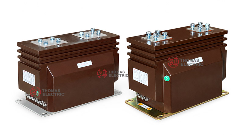
Product Display
 Indoor Epoxy Cast-Resin Current Transformer Thomas Electric")
Applications
- Indoor 10kV, 11kV and 12kV class medium-voltage switchgear
- Incoming feeder panels and outgoing feeder panels with high-current busbar connection
- Energy metering cabinets requiring dedicated metering accuracy cores
- Protection relay systems requiring 10P, 10P15, 10P20, 5P or 5P20 class cores
- SCADA, power monitoring, automation and feeder supervision circuits
- Switchgear projects requiring one platform with optional 2S or 4S secondary configuration
Features
- Shared C8/210 platform: The 2S and 4S products use the same 210 structural family, making selection easier for projects with different secondary circuit requirements.
- Dual configuration options: 2S is suitable for measurement plus protection; 4S is suitable for metering, indication, protection and backup protection in one CT body.
- Wide primary current range: The supplied data covers current selections from low-current ratios up to 6000A for high-current switchgear applications.
- High-current terminal layouts: Different primary terminal drawings are available for 5A–1000A, 1200A–3150A and 4000A–6000A ranges.
- Cast-resin insulation system: The primary conductor, secondary windings and magnetic cores are enclosed in epoxy resin for stable indoor insulation and mechanical support.
- IEC-oriented selection: The product can be selected for international 10kV, 11kV and 12kV class networks with 12/42/75kV insulation coordination.
Principle
The LZZBJ9-10C8/210 current transformer converts primary current into a proportional secondary current signal by electromagnetic induction. The primary current produces magnetic flux in the magnetic core, while the secondary winding supplies a standardized 5A or 1A signal to meters, relays, monitoring devices or automation systems. The epoxy cast-resin body provides insulation between the medium-voltage primary circuit and the low-voltage secondary circuits.
For the 2S configuration, each secondary circuit is normally assigned a clear role, such as measurement and protection. For the 4S configuration, multiple independent secondary cores can be assigned to metering, measurement, protection and backup protection. Each core should be selected by accuracy class, rated output, burden, terminal marking and protection performance instead of treating the CT as a single-output device.
Model Designation
 Indoor Epoxy Cast-Resin Current Transformer Thomas Electric")
The model code can be interpreted as follows:
| Code | Meaning |
|---|---|
| L | Current transformer |
| Z | Indoor type / support structure |
| Z | Epoxy resin casting insulation |
| B | Protection level available |
| J | Strengthened design |
| 9 | Design serial number |
| 10 | 10kV catalogue voltage class; applicable to 10kV, 11kV and 12kV class systems when insulation coordination is confirmed |
| C8 | Structure / design platform code |
| 210 | Nominal structure width / installation dimension code |
| 2S | Dual-secondary schematic configuration |
| 4S | Multi-secondary schematic configuration |
Technical Data
| Item | Specification |
|---|---|
| Rated voltage class | 10kV, 11kV and 12kV class indoor systems |
| Rated insulation level | 12/42/75kV |
| Rated frequency | 50Hz |
| Rated secondary current | 5A or 1A |
| Rated primary current range | 5A to 6000A reference range according to model and configuration |
| 2S accuracy combinations | 0.2/0.5, 0.2/10P20, 0.5/10P20, 0.2/10P25, 0.5/10P25, 0.2/10P30, 0.5/10P30 and project-specific combinations |
| 4S accuracy combinations | 0.2/0.5/5P/5P, 0.5/0.5/5P/5P, 0.2/5P/5P, 0.5/5P/5P and project-specific combinations |
| Rated output | 10VA to 150VA depending on rated primary current, secondary configuration and accuracy class |
| Rated short-time thermal current | Up to 180kA/1s reference for high-current configurations |
| Rated dynamic current | Up to 260kA reference for high-current configurations |
| Creepage distance | 330mm reference according to supplied data |
| Approximate weight | 58kg reference according to supplied data |
| Applicable standards | GB 20840.2-2014, IEC 61869-2:2012 and special project requirements |
2S Configuration
The LZZBJ9-10C8/210/2S version is used when two secondary circuits are required. It is suitable for projects where one secondary output is assigned to measurement or metering and another output is assigned to relay protection.
| Rated
Primary Current (A) |
Typical
Accuracy Combination |
Rated
Output Reference |
Short-Time
Thermal Current |
Rated
Dynamic Current |
|---|---|---|---|---|
| 5–300 | 0.2 / 0.5 | 20VA | 150 × I1n | 375 × I1n |
| 400–600 | 0.2 / 10P20 0.5 / 10P20 |
20VA / 40VA | 45kA to 80kA | 112.5kA to 160kA |
| 800–1250 | 0.2 / 10P25 0.5 / 10P25 |
40VA / 40VA | 80kA to 100kA | 160kA to 180kA |
| 1500–3150 | 0.2 / 10P30 0.5 / 10P30 |
40VA / 40VA | 100kA to 180kA | 180kA to 260kA |
| 4000–6000 | Project-specific 2S combination | By agreement | By agreement | By agreement |
4S Configuration
The LZZBJ9-10C8/210/4S version is used when several secondary functions are required in one CT body. It is suitable for complex switchgear schemes with metering, monitoring, protection and backup protection circuits.
| Rated
Primary Current (A) |
Typical
Accuracy Combination |
Rated
Output Reference |
Short-Time
Thermal Current |
Rated
Dynamic Current |
|---|---|---|---|---|
| 15–100 | 0.2 / 0.5 / 0.5 / 5P 0.5 / 0.5 / 5P / 5P |
15 / 25 / 35VA reference | 2kA to 31.5kA | 5kA to 80kA |
| 150–600 | 0.2 / 0.5 / 5P / 5P | 20 / 40 / 50 / 75VA reference | 31.5kA to 80kA | 80kA to 160kA |
| 750–1250 | 0.2 / 0.5 / 5P / 5P | 50 / 75 / 100VA reference | 80kA to 100kA | 160kA to 180kA |
| 1500–3150 | 0.2 / 0.5 / 5P / 5P | 100 / 150VA reference | 100kA | 160kA to 200kA |
| 4000–6000 | Project-specific 4S combination | By agreement | By agreement | By agreement |
Note: The above values are arranged from the supplied technical tables for website selection reference. Final ratio, secondary current, accuracy combination, rated output, short-time thermal current, dynamic current and terminal markings shall follow the nameplate, approved drawing and factory test report.
Terminals
Primary terminals are marked as P1 / P2. Secondary terminal marking depends on the 2S or 4S configuration. For 2S, typical secondary terminals include 1S1 / 1S2 and 2S1 / 2S2. For 4S, additional terminals such as 3S1 / 3S2 and 4S1 / 4S2 may be used. The final terminal arrangement must be confirmed by the approved wiring diagram.
| Terminal Group | 2S Version | 4S Version | Engineering Note |
|---|---|---|---|
| Primary | P1 / P2 | P1 / P2 | Primary direction and busbar connection shall follow the outline drawing. |
| First secondary | 1S1 / 1S2 | 1S1 / 1S2 | Usually used for metering or measurement. |
| Second secondary | 2S1 / 2S2 | 2S1 / 2S2 | Usually used for protection or monitoring. |
| Additional secondary | Not applicable or project-specific | 3S1 / 3S2, 4S1 / 4S2 | Used for backup protection, automation or additional relay circuits. |
Busbar Layout
| Current Range | Primary Layout Reference |
Design Focus |
|---|---|---|
| I1n: 5A–1000A | Standard primary terminal layout | Used for lower and medium current switchgear panels. |
| I1n: 1200A–3150A | High-current terminal layout | Requires confirmation of busbar spacing, bolt holes and cabinet clearance. |
| I1n: 4000A–6000A | Large high-current terminal layout | Requires detailed drawing confirmation before copper busbar processing. |
Service Conditions
- Installation location: indoor medium-voltage switchgear
- System voltage: 10kV, 11kV and 12kV class networks
- Rated frequency: 50Hz
- Rated secondary current: 5A or 1A
- Ambient temperature: -5°C to +40°C
- The installation environment should be free from severe vibration, conductive dust, corrosive gas, explosive medium, heavy pollution and abnormal condensation.
- For high-current applications, temperature rise, busbar connection, ventilation and cabinet clearance shall be reviewed together.
Standards and Compliance
The LZZBJ9-10C8/210/2S and LZZBJ9-10C8/210/4S current transformers can be supplied according to GB 20840.2-2014, IEC 61869-2:2012 and special project requirements. For international product pages, this series should be described as an indoor epoxy cast-resin current transformer for 10kV, 11kV and 12kV class switchgear. Routine tests generally include ratio test, polarity verification, accuracy test, dielectric withstand test, insulation inspection and appearance inspection.
Installation and Dimensions
 Indoor Epoxy Cast-Resin Current Transformer Thomas Electric")
 Indoor Epoxy Cast-Resin Current Transformer Thomas Electric")
The C8/210 structure uses an indoor support-type body with top primary terminals and lower secondary terminal arrangement. The supplied drawings show different primary layouts for 5A–1000A, 1200A–3150A and 4000A–6000A current ranges. Cabinet engineers should confirm the outline drawing before switchgear production, especially for high-current busbar layouts.
Dimensions
| Item | Dimension / Note |
|---|---|
| Structure code | C8/210 support-type design |
| Secondary schematic | 2S dual-secondary or 4S multi-secondary |
| Primary terminal arrangement | Different layouts for 5A–1000A, 1200A–3150A and 4000A–6000A |
| Creepage distance | 330mm reference |
| Approximate weight | 58kg reference |
| Drawing confirmation | Required before switchgear production, replacement or busbar fabrication |
Safety Notes
- Confirm whether the project requires the 2S or 4S configuration before ordering.
- Check primary busbar size, bolt spacing, contact surface and phase clearance before switchgear production.
- Use the correct primary terminal drawing for the selected current range.
- Confirm all secondary terminal markings before connecting meters, relays or monitoring devices.
- The secondary circuit of a current transformer must not be open-circuited when the primary circuit is energized.
- Before disconnecting instruments or relays, short-circuit the corresponding secondary circuit through a proper shorting block.
- Installation and maintenance shall be performed by qualified medium-voltage electrical personnel.
Ordering Info
- Product model: LZZBJ9-10C8/210/2S or LZZBJ9-10C8/210/4S
- Rated primary current and rated secondary current
- 2S or 4S secondary schematic requirement
- Accuracy class combination and rated output for each secondary circuit
- Rated insulation level and applicable IEC / GB standard
- Required short-time thermal current and rated dynamic current
- Primary terminal drawing, busbar hole size and mounting dimension requirement
- Switchgear layout, cabinet clearance and primary terminal direction
- Quantity, certificates, routine test reports, labeling and packaging requirements
Selection Guide
- Choose 2S or 4S: Select 2S for basic measurement plus protection, or 4S for metering, monitoring, protection and backup protection.
- Confirm current range: Match the rated primary current with the correct busbar layout: 5A–1000A, 1200A–3150A or 4000A–6000A.
- Define core function: Specify each secondary core by function, accuracy class, output and burden.
- Check protection performance: Confirm 10P, 5P or project-specific protection class according to relay settings and fault-current level.
- Verify high-current withstand: Review thermal current, dynamic current, contact area and temperature rise for high-current applications.
- Review cabinet space: Confirm secondary terminal access, cable bending space, grounding point and shorting terminal arrangement.
- Approve final drawing: Confirm outline dimensions, terminal diagram, nameplate data and routine test requirements before production.