Product Overview
The LZZBJ9-12/150b/4S current transformer, also supplied under the alternative designation AS12/150b/4S, is a 12kV indoor single-phase epoxy resin cast current transformer for medium-voltage switchgear. It is designed for current measurement, electric energy metering, feeder supervision, protection relaying and auxiliary monitoring in 10kV, 11kV and 12kV class power distribution systems.
This model belongs to the compact 150b body-width platform, but unlike the 150b/2S version, the 150b/4S configuration is intended for projects that require multiple secondary outputs in a limited installation space. It is suitable when one CT must serve different circuits at the same time, for example revenue metering, panel indication, relay protection and backup protection. The epoxy resin cast body encloses the primary conductor, secondary windings and annular cores, forming a dry-type, fully enclosed insulation system.
Product Type
| Item | Specification |
|---|---|
| Product name | 12kV Indoor Single-Phase Epoxy Resin Cast Current Transformer |
| Model series | LZZBJ9-12/150b/4S / AS12/150b/4S |
| Structure | Indoor, dry-type, fully enclosed, support-type epoxy cast-resin structure |
| Voltage class | 10kV, 11kV and 12kV class medium-voltage systems |
| Highest voltage for equipment | 12kV class |
| Rated insulation level | 12/28/75kV according to supplied data; 12/42/75kV may be specified by project requirement |
| Rated frequency | 50Hz / 60Hz |
| Secondary current | 5A or 1A |
| Secondary structure | 4S multi-secondary configuration |
| Installation site | Indoor switchgear |
| Applications | Current measurement, energy metering, protection relaying, backup protection and monitoring |
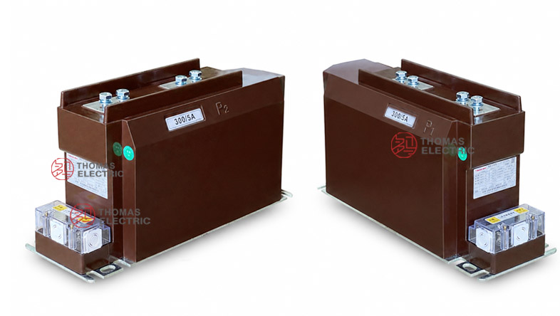
Product Display


The product is built for indoor service conditions where pollution resistance, humidity resistance, compact mounting and reliable secondary wiring are important. It is commonly used in metal-clad switchgear, incoming panels, feeder cabinets and metering panels. Final selection shall be based on the approved drawing, current ratio, secondary current, accuracy combination, rated output, short-time thermal current and rated dynamic current.
Applications
- 12kV-class indoor switchgear used in 10kV, 11kV and 12kV distribution networks
- Compact feeder panels requiring multiple CT secondary outputs in one body
- Revenue metering circuits requiring dedicated accuracy cores
- Protection relay circuits requiring 10P, 10P15 or 10P20 performance
- Power monitoring, energy management, SCADA and automation systems
- Switchgear retrofit projects where 150b body width and 4S secondary layout must be maintained
Features
- Compact 150b platform: The 150b body width is suitable for switchgear designs with limited space while still supporting multi-secondary functionality.
- 4S multi-secondary output: Four secondary circuits can be assigned to different functions such as metering, measurement, protection and backup protection.
- Dry-type epoxy insulation: The primary and secondary windings with the annular core are encapsulated in epoxy resin to support stable indoor insulation performance.
- IEC-oriented application: The product follows the technical direction of IEC 60044-1 and may be specified according to IEC 61869-1 and IEC 61869-2 for international projects.
- Flexible installation: The fully enclosed support construction allows practical switchgear integration when the terminal direction and mounting holes are confirmed by drawing.
- Moisture and pollution resistance: The resin body is designed for indoor environments where humidity, dust and surface contamination must be considered.
Principle
The LZZBJ9-12/150b/4S current transformer converts primary current into standardized secondary current through electromagnetic induction. The primary current generates magnetic flux in the annular core, and the secondary windings deliver proportional outputs to meters, relays or monitoring equipment. The epoxy resin body provides the required insulation barrier between the primary medium-voltage circuit and the secondary low-voltage circuits.
Because this is a 4S configuration, each secondary circuit should be selected and checked as an independent functional circuit. A metering core must maintain ratio and phase accuracy within the rated burden, while a protection core must maintain the required accuracy limit behavior under fault-current conditions. For reliable engineering selection, accuracy class, rated output, cable burden, relay burden, thermal current and dynamic current must be reviewed together.
Model Designation

The model code can be interpreted as follows:
| Code | Meaning |
|---|---|
| L | Current transformer |
| Z | Indoor / pillar-type structure |
| Z | Epoxy resin casting insulation |
| B | Protection level available |
| J | Strengthened design |
| 9 | Design serial number |
| 12 | 12kV maximum operating voltage class |
| 150b | Compact nominal width / structure dimension code |
| 4S | Four-secondary schematic code |
| AS12 | Alternative 12kV series designation used for the same CT platform |
Technical Data
| Item | Specification |
|---|---|
| Rated voltage class | 10kV, 11kV and 12kV class indoor systems |
| Highest voltage for equipment | 12kV class |
| Rated insulation level | 12/28/75kV; optional insulation coordination shall follow project specification |
| Rated frequency | 50Hz / 60Hz |
| Rated primary current | 20A to 1250A reference range according to sample data; special ratios by technical agreement |
| Rated secondary current | 5A or 1A |
| Accuracy combination | 0.2/0.2/5P10, 0.2/0.5/5P15, 0.2/0.5/5P20, 0.2/5P10/10P15, 0.5/5P10/10P20 and project-specific combinations |
| Rated output | 10/10/30, 10/15/20, 10/20/20, 15/15/15, 15/20/20 or project-specific VA configuration |
| Ambient temperature | -5°C to +40°C |
| Insulating medium | Epoxy resin |
| Installation type | Indoor support-type / busbar-type switchgear installation |
| Applicable standards | IEC 60044-1; IEC 61869-1 and IEC 61869-2 may be used for international projects |
Terminals
The 4S schematic indicates a multi-secondary arrangement in a compact 150b body. Typical terminal markings include P1 / P2 for the primary circuit and 1S1 / 1S2, 2S1 / 2S2, 3S1 / 3S2 and 4S1 / 4S2 for the secondary circuits. The final terminal layout shall follow the nameplate, wiring diagram and approved outline drawing.
| Terminal Marking |
Function | Application Note |
|---|---|---|
| P1 / P2 | Primary terminals | Primary current direction and busbar connection shall follow the project wiring diagram. |
| 1S1 / 1S2 | First secondary core | Often assigned to metering or precision measurement. |
| 2S1 / 2S2 | Second secondary core | Can be used for panel indication, monitoring or auxiliary measurement. |
| 3S1 / 3S2 | Third secondary core | Usually assigned to relay protection. |
| 4S1 / 4S2 | Fourth secondary core | Used for backup protection or project-specific secondary function. |
Selection Table
The following selection table summarizes typical 150b/4S ratio ranges and secondary configurations. Long accuracy and output values are wrapped into multiple lines to keep the table readable in responsive website layouts.
| Rated
Primary Current (A) |
Accuracy
Class Combination |
Rated
Output (VA) |
Short-Time
Thermal Current |
Rated
Dynamic Current (kA) |
|---|---|---|---|---|
| 20, 30, 40 50, 75, 100 |
0.2 / 0.2 / 5P10 0.2 / 0.5 / 5P15 0.2 / 0.5 / 5P20 0.2 / 5P10 / 10P15 0.5 / 5P10 / 10P20 |
10 / 10 / 30 10 / 15 / 20 10 / 20 / 20 |
150 × I1n | 375 × I1n |
| 150, 200 | 31.5kA | 80 | ||
| 300, 400 | 10 / 10 / 40 10 / 15 / 20 15 / 15 / 15 |
45kA | 112.5 | |
| 500 | 63kA | 130 | ||
| 600, 800 | 63kA | 130 | ||
| 1000, 1200, 1250 | 0.2 / 0.2 / 5P10 0.2 / 0.5 / 5P20 0.5 / 5P10 / 10P20 |
15 / 20 / 20 15 / 15 / 20 20 / 15 / 15 |
80kA | 160 |
Note: The above data is for preliminary selection. Final current ratio, secondary current, rated output, accuracy class, thermal current, dynamic current and terminal arrangement shall be confirmed according to the nameplate, approved drawing and factory test report.
Structure Reference
| Structure | Engineering Purpose |
Selection Note |
|---|---|---|
| 150b | Compact-width support body | Used where switchgear width is limited but multiple secondary circuits are still required. |
| 4S | Four secondary functions | Suitable for separating metering, indication, protection and backup protection. |
| AS12 | IEC-style model designation | Useful for export projects requiring 12kV class naming and documentation. |
Service Conditions
- Installation site: indoor medium-voltage switchgear
- System voltage: 10kV, 11kV and 12kV class networks
- Rated frequency: 50Hz / 60Hz
- Ambient temperature: -5°C to +40°C
- The installation environment should be free from severe vibration, conductive dust, corrosive gas, explosive medium, heavy pollution and abnormal condensation.
- For high altitude, coastal, humid or high-pollution applications, the insulation requirement and creepage distance should be technically confirmed.
Standards and Compliance
The LZZBJ9-12/150b/4S current transformer is designed for IEC-oriented medium-voltage CT applications and can be supplied according to IEC 60044-1. For newer international project specifications, IEC 61869-1 and IEC 61869-2 may also be used as the reference standards. Routine test items generally include ratio test, polarity verification, accuracy test, dielectric withstand test, insulation inspection and appearance inspection.
Installation and Dimensions

The product adopts a compact 150b support-type structure with top primary terminals and bottom secondary terminal arrangement. Since the 4S version includes more secondary circuits than the 2S version, enough wiring space must be reserved around the secondary terminal box. The switchgear manufacturer should confirm busbar spacing, primary terminal direction, mounting hole position and secondary cable route before production.
Dimensions
| Item | Dimension / Note |
|---|---|
| Structure code | 150b compact support-type design |
| Secondary schematic | 4S multi-secondary arrangement |
| Primary terminal arrangement | Confirmed according to ratio and approved drawing |
| Secondary terminal layout | Multiple secondary terminals arranged according to 4S schematic |
| Approximate weight | About 34kg according to supplied sample drawing |
| Drawing confirmation | Required before switchgear production or replacement |
Safety Notes
- Confirm the complete model name, including 150b and 4S, before installation.
- Check the switchgear mounting space, primary terminal clearance and secondary terminal wiring area.
- Identify every secondary core before wiring to avoid mixing metering and protection circuits.
- Connect P1/P2 and all secondary terminals according to polarity markings and the wiring diagram.
- The secondary circuit of a current transformer must not be open-circuited when the primary circuit is energized.
- Before disconnecting instruments or relays, short-circuit the corresponding secondary circuit through a proper shorting block.
- Installation and maintenance shall be performed by qualified medium-voltage electrical personnel.
Ordering Info
- Product model: LZZBJ9-12/150b/4S or AS12/150b/4S
- Rated primary current and rated secondary current
- Accuracy class combination for each secondary core
- Rated output / burden for each secondary circuit
- Rated insulation level and applicable IEC standard
- Required short-time thermal current and rated dynamic current
- Secondary terminal marking and 4S schematic requirement
- Switchgear layout, mounting dimensions and primary terminal direction
- Quantity, certificates, routine test reports, labeling and packaging requirements
Selection Guide
- Confirm voltage class: Select this model for 10kV, 11kV and 12kV class indoor switchgear.
- Confirm space limit: Use the 150b structure when cabinet width is limited but multiple secondary outputs are still required.
- Define four functions: Assign each secondary core to metering, measurement, relay protection or backup protection before quotation.
- Select ratio and output: Match the current ratio and rated output with the connected meters, relays and secondary cable burden.
- Check protection level: Confirm 5P, 10P or other protection classes according to relay setting and fault-current requirement.
- Verify terminal layout: Ensure enough wiring space for all 4S secondary terminals in the switchgear design.
- Approve drawings: Confirm outline dimensions, mounting holes, polarity markings and terminal labels before production.