Product Overview
The JSZW3-6 / JSZW3-10 / JSZW3-11 / JSZW3-12 voltage transformer is an indoor three-phase epoxy cast-resin voltage transformer for medium-voltage switchgear and distribution systems. It is designed for voltage measurement, energy metering, voltage monitoring, residual voltage detection and relay protection in AC power systems with rated frequency of 50Hz or 60Hz.
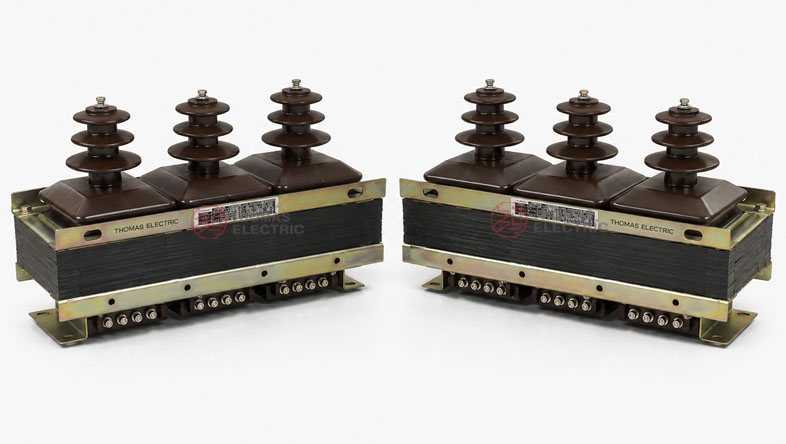
This product is a three-phase semi-enclosed epoxy cast-resin voltage transformer. The iron core uses a side-iron core-type structure made of cold-rolled silicon steel sheet. The primary winding, secondary metering winding and residual-voltage winding are concentrically wound on the core and cast with epoxy resin. The three phases are integrated and fixed together, forming a compact indoor VT/PT assembly suitable for switchgear installation.
For international product pages, this series should not be limited to the Chinese 6kV / 10kV naming convention. It is better to present the product as a 6kV, 10kV, 11kV and 12kV class indoor three-phase voltage transformer. For IEC-oriented export projects, the 11kV and 12kV class wording helps match common medium-voltage systems in Southeast Asia, the Middle East, Africa and other international markets. Final voltage ratio, insulation level and accuracy class shall be confirmed according to the project specification and nameplate.
Product Type
| Item | Specification |
|---|---|
| Product name | Indoor Three-Phase Semi-Enclosed Epoxy Cast-Resin Voltage Transformer |
| Model series | JSZW3-6 / JSZW3-10 / JSZW3-11 / JSZW3-12 |
| Product structure | Three-phase integrated, semi-enclosed epoxy resin casting type |
| Voltage class | 6kV, 10kV, 11kV and 12kV class indoor medium-voltage systems |
| Rated frequency | 50Hz / 60Hz |
| Typical voltage ratio | 6kV / √3 : 100V / √3 : 100V / 3; 10kV / √3 : 100V / √3 : 100V / 3; 11kV / √3 : 110V / √3 : 110V / 3 by project requirement |
| Accuracy classes | Metering: 0.2, 0.5 or 1; Protection / residual voltage: 3P or 6P |
| Maximum output | 600VA reference |
| System neutral | Suitable for systems where the neutral point is not effectively grounded |
| Installation type | Type A side installation or Type B base installation |
Product Display

Applications
- 6kV, 10kV, 11kV and 12kV class indoor medium-voltage switchgear
- Voltage measurement and energy metering circuits
- Relay protection, voltage supervision and signal acquisition circuits
- Residual voltage / open-delta voltage detection in ungrounded or non-effectively grounded systems
- Incoming cabinets, metering cabinets, feeder panels and distribution switchgear
- IEC-oriented projects requiring 11kV or 12kV class voltage transformer documentation
Features
- Three-phase integrated design: A single compact unit provides three-phase voltage transformation, reducing cabinet wiring complexity and installation space.
- Semi-enclosed epoxy casting: The primary winding, secondary winding and residual voltage winding are cast with epoxy resin for insulation stability and mechanical strength.
- Residual-voltage winding: The product supports open-delta residual voltage output for earth-fault detection and relay protection schemes.
- International voltage coverage: The product page can include 6kV, 10kV, 11kV and 12kV class systems, making it more suitable for IEC and export markets.
- Metering and protection accuracy: 0.2 / 0.5 / 1 metering classes and 3P / 6P protection classes can be selected according to the application.
- Two installation forms: Type A is side-mounted with installation holes on the iron-core clamp, while Type B uses a base for installation.
Principle
The JSZW3 voltage transformer works according to electromagnetic induction. The primary winding is connected to the medium-voltage system, and the secondary winding provides a reduced standard voltage signal for meters, protection relays and monitoring devices. The residual-voltage winding can be connected in open-delta form to detect zero-sequence voltage during earth-fault conditions.
The product is mainly used in non-effectively grounded neutral systems. The primary winding and terminal A are fully insulated, while terminal N is not fully insulated according to the product structure. Therefore, the wiring method, system grounding mode and secondary circuit connection must follow the approved wiring diagram and project specification.
Model Designation

Technical Data
| Item | Specification |
|---|---|
| Model series | JSZW3-6 / JSZW3-10 / JSZW3-11 / JSZW3-12 |
| Rated voltage class | 6kV, 10kV, 11kV and 12kV class indoor systems |
| Rated insulation level | 7.2/32/60kV for 6kV class; 12/42/75kV for 10kV, 11kV and 12kV class by project confirmation |
| Rated frequency | 50Hz / 60Hz |
| Ambient temperature | -5°C to +40°C |
| Voltage transformer type | Three-phase semi-enclosed epoxy cast-resin inductive voltage transformer |
| Core structure | Side-iron core-type structure using cold-rolled silicon steel sheet |
| Accuracy class | 0.2 / 0.5 / 1 for metering; 3P / 6P for protection or residual voltage circuit |
| Maximum output | 600VA reference |
| Applicable standards | IEC 61869-3, IEC 61869-1, GB/T 20840.3-2013, GB/T 20840.1-2010 and project-specific requirements |
Selection Table
The table below organizes the catalogue data and adds international voltage-ratio guidance for 11kV / 12kV class projects. Long table cells are split into multiple lines for responsive website display.
| Model | Rated Voltage Ratio |
Accuracy Class Combination |
Rated Output (VA) |
Maximum Output (VA) |
|---|---|---|---|---|
| JSZW3-6 | 6000 / √3 : 100 / √3 : 100 / 3 | 0.2 / 6P or 0.2 / 3P | 45 / 120 | 600 |
| 0.5 / 6P or 0.5 / 3P | 90 / 120 | |||
| 1 / 6P or 1 / 3P | 150 / 120 | |||
| JSZW3-10 | 10000 / √3 : 100 / √3 : 100 / 3 | 0.2 / 6P or 0.2 / 3P | 60 / 120 | 600 |
| 0.5 / 6P or 0.5 / 3P | 150 / 120 | |||
| 1 / 6P or 1 / 3P | 240 / 240 | |||
| JSZW3-11 | 11000 / √3 : 110 / √3 : 110 / 3 or project-specified ratio |
0.2 / 3P or 0.2 / 6P | By technical agreement | 600 reference |
| 0.5 / 3P or 0.5 / 6P | By technical agreement | |||
| 1 / 3P or 1 / 6P | By technical agreement | |||
| JSZW3-12 | 12000 / √3 : 110 / √3 : 110 / 3 or project-specified ratio |
0.2 / 3P or 0.2 / 6P | By technical agreement | 600 reference |
| 0.5 / 3P or 0.5 / 6P | By technical agreement | |||
| 1 / 3P or 1 / 6P | By technical agreement |
Note: Only one rated output and its corresponding accuracy class should be selected for each winding unless otherwise specified. Parameters beyond the listed catalogue range may be determined by technical agreement between manufacturer and purchaser.
Wiring Diagram

The JSZW3 series normally includes primary windings, metering secondary windings and residual-voltage windings. Typical terminal marking follows three-phase VT conventions. The primary terminals are marked A, B, C and N. The secondary metering terminals may be marked a, b, c, n, and the residual-voltage winding may be marked da / dn or equivalent according to the wiring diagram.
| Winding / Terminal | Function | Engineering Note |
|---|---|---|
| A, B, C | Primary phase terminals | Connected to the medium-voltage three-phase system. |
| N | Primary neutral terminal | Terminal N is not fully insulated; wiring must follow the approved system grounding arrangement. |
| a, b, c, n | Metering secondary terminals | Used for voltage meters, energy meters and monitoring devices. |
| da / dn | Residual-voltage winding | Used for open-delta residual voltage output and earth-fault detection. |
| 1a, 1b, 1c / 2a, 2b, 2c | Multi-secondary terminals | Used where separate metering and protection secondary circuits are required. |
The product can be supplied with different secondary wiring arrangements. The catalogue shows Y / Δ connection for three-winding voltage transformer wiring and Y / Y / Δ connection for four-winding voltage transformer wiring. The final terminal arrangement must be confirmed according to the approved wiring diagram, secondary winding quantity and protection scheme.
Service Conditions
- Installation location: indoor medium-voltage switchgear
- Rated frequency: 50Hz / 60Hz
- Ambient temperature: -5°C to +40°C
- Suitable system: neutral point not effectively grounded or isolated-neutral systems
- The installation environment should be free from severe vibration, conductive dust, corrosive gas, explosive medium and heavy pollution.
- For high altitude, high humidity, tropical climate or special utility requirements, technical confirmation is recommended before ordering.
Standards and Compliance
The JSZW3 series voltage transformer can be specified according to IEC 61869-3 for inductive voltage transformers and IEC 61869-1 for general instrument transformer requirements. Catalogue references also include GB/T 20840.3-2013 and GB/T 20840.1-2010. For international projects, IEC wording is recommended in the product page, while GB references can be retained as factory design and test references.
Installation and Dimensions

Dimensions
| Dimension Item | Reference Value | Engineering Note |
|---|---|---|
| Phase spacing | 139 ± 1mm | Reference spacing between high-voltage bushings. |
| Overall width | 487mm reference | Used for switchgear layout and mounting space confirmation. |
| Installation hole spacing | 445 ± 1mm reference | Base mounting reference from catalogue drawing. |
| Overall height | 270 ± 3mm reference | Confirm cabinet height and top clearance before installation. |
| Depth reference | 195mm reference | Used for side clearance and installation planning. |
| Long mounting holes | 4-20 × 13mm reference | Mounting holes shall be confirmed with the approved drawing. |
Dimension data is for preliminary cabinet layout. Final dimensions are subject to the approved outline drawing.
Type A and Type B installation forms are available. Type A is installed on the side, with installation holes on the iron-core clamp. Type B uses a base for installation. Before switchgear production, confirm the mounting hole distance, phase spacing, bushing clearance, secondary terminal direction, wiring diagram and grounding arrangement according to the approved outline drawing.
Safety Notes
- Confirm voltage class, voltage ratio, insulation level, accuracy class and rated output before production.
- Check the system grounding method before selecting the wiring diagram.
- Terminal N is not fully insulated; it must be connected only according to the approved design.
- Secondary circuits of voltage transformers shall not be short-circuited during operation.
- Before maintenance, de-energize the primary circuit and follow lockout/tagout safety procedures.
- One point of the secondary circuit should be grounded according to project electrical safety practice.
- Installation and commissioning shall be performed by qualified medium-voltage electrical personnel.