Product Overview
The LAJ-10Q / LFZJ-10Q current transformer is an indoor epoxy resin cast wall-through current transformer designed for current measurement, power measurement, and relay protection in medium-voltage AC systems. It is suitable for rated frequency of 50Hz or 60Hz and rated voltage class of 10kV. For international projects, it can be positioned for 10kV, 11kV and 12kV class indoor switchgear applications, subject to insulation level and project confirmation.
This series adopts a resin casting insulated structure. For primary currents up to 300A, the product is generally a semi-enclosed structure, while higher current ranges use a more enclosed single-wire configuration to improve external insulation performance. The product is intended for indoor switchgear, distribution cabinets, and medium-voltage assemblies where compact wall-through installation, stable metering performance, and protection coordination are required.
Product Type
| Item | Specification |
|---|---|
| Product name | Indoor Wall-Through Epoxy Resin Cast Current Transformer |
| Model series | LAJ-10Q / LFZJ-10Q |
| Product structure | Wall-through type, resin casting insulation, compact indoor structure |
| Voltage class | 10kV class; applicable to 10kV, 11kV and 12kV class indoor systems by project confirmation |
| Rated frequency | 50Hz / 60Hz |
| Secondary current | 5A or 1A |
| Typical use | Current measurement, power measurement, metering, relay protection |
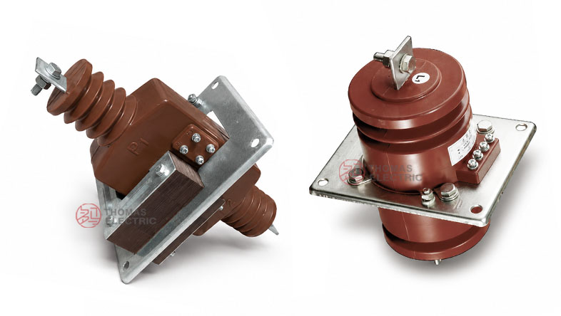
Product Display


The catalogue shows two corresponding designations, LAJ-10Q and LFZJ-10Q, for the same indoor wall-through resin cast CT family. Final model marking, outline size, and ratio range should be confirmed against the approved drawing and nameplate.
Applications
- Indoor medium-voltage switchgear and distribution panels
- 10kV, 11kV and 12kV class power distribution systems
- Current measurement and power measurement circuits
- Relay protection and feeder monitoring circuits
- Wall-through installation in fixed cabinet structures
- Industrial substations and complete electrical equipment
Features
- Wall-through structure: Suitable for cabinet panel installation where the primary conductor passes through the CT body.
- Resin cast insulation: Epoxy/resin casting improves insulation stability and environmental resistance for indoor medium-voltage service.
- Metering and protection support: Available for accuracy classes 0.2, 0.5, 1 and protection class 10P10.
- Multi-ratio range: Covers low to high primary currents for metering feeders, distribution circuits, and protection applications.
- Dual secondary option: Rated secondary current may be specified as 5A or 1A according to project requirements.
- Compact cabinet integration: Designed for practical installation in indoor switchgear with matching hole dimensions and outline variants.
Principle
The LAJ-10Q / LFZJ-10Q current transformer works on the principle of electromagnetic induction. When current flows through the primary conductor, magnetic flux is generated in the core and induces a proportional current in the secondary winding. This secondary signal is supplied to connected measuring instruments, meters, or protection relays while maintaining electrical isolation between the medium-voltage primary circuit and the low-voltage secondary circuit.
Model Designation

The model code can be interpreted as follows:
| Code | Meaning |
|---|---|
| L | Current transformer |
| A | Wall-through type |
| J | Extended output / enhanced output design |
| 10 | Rated voltage class: 10kV class |
| Q | Stiffening / reinforced type |
| LFZJ-10Q | Corresponding model designation used in some catalogues for the same product family |
Technical Data
| Item | Specification |
|---|---|
| Rated insulation level | 11.5/42/75kV |
| Artificial pollution class | Class 2, based on catalogue note |
| Rated frequency | 50Hz / 60Hz |
| Rated secondary current | 5A or 1A |
| Power factor for burden | 0.8 (lagging) |
| Partial discharge reference | According to GB5583-85 and IEC44-4, apparent partial discharge not more than 60pC |
| Accuracy classes | 0.2, 0.5, 1, 10P10 |
| Installation | Indoor wall-through mounting |
Selection Table
The selection table below is arranged by current ratio and follows the catalogue structure shown in your reference image. Long headers are split into multiple lines for cleaner website display.
| Rated primary
current Current ratio |
Accuracy
class 0.2 |
Accuracy
class 0.5 |
Accuracy
class 1 |
Protection
class 10P10 |
Thermal
current kA (r.m.s) / 1s |
Dynamic
current kA (peak) |
|---|---|---|---|---|---|---|
| 5/5, 10/5, 15/5, 20/5, 30/5, 40/5, 50/5, 75/5, 100/5, 150/5, 200/5 | 10VA | 10VA | 10VA | 15VA | 90 × In | 160 × In |
| 300/5, 400/5 | 10VA | 10VA | 10VA | 15VA | 75 × In | 135 × In |
| 500/5 | 10VA | 10VA | 10VA | 15VA | 60 × In | 110 × In |
| 600/5, 800/5, 1000/5, 1500/5 | 25VA | 25VA | 25VA | 20VA | 50 × In | 90 × In |
Note: The above selection table is structured from the catalogue image and should be finally confirmed against the manufacturer drawing, approved technical data sheet, and nameplate before ordering.
Service Conditions
- Installation location: indoor medium-voltage switchgear
- Ambient frequency: 50Hz or 60Hz
- The installation environment should be free from severe vibration, corrosive gas, explosive medium, conductive dust, and abnormal condensation.
- For international projects, final service conditions should be checked against altitude, pollution degree, humidity, and insulation coordination requirements.
Standards and Compliance
According to the catalogue, this series references GB5583-85 and IEC44-4 for partial discharge related requirements, and is used as an indoor medium-voltage current transformer for measurement and protection applications. For export or international projects, the final applicable IEC/GB standard combination should be defined in the project specification.
Installation and Dimensions


The catalogue provides both hole dimensions and overall dimensions for different current ranges. The 5–300/5 and 400–800/5 ranges use different outline arrangements, so the cabinet cut-out and mounting layout should be selected according to the exact current ratio and product drawing.
Dimensions
| Item | Dimension / Note |
|---|---|
| Hole dimension group A | Used for LAJ-10 5–300/5 and corresponding lower-current range drawings |
| Hole dimension group B | Used for LAJ-10 400–800/5 and corresponding higher-current range drawings |
| Overall dimension variants | Different outline sizes are used for 20–300/5 and 400–1500/5 current ranges |
| Weight | Catalogue reference indicates approx. 19kg for one shown configuration |
| Engineering check | Confirm cut-out, clearance, terminal direction, and busbar/conductor arrangement before cabinet fabrication |
Safety Notes
- Confirm model designation, current ratio, secondary current, and accuracy class before installation.
- Match the selected CT with the correct cabinet opening and mounting arrangement.
- Ensure the burden of connected meters, relays, and secondary wiring does not exceed the rated output of the selected class.
- The CT secondary circuit must not be open-circuited while the primary circuit is energized.
- Before disconnecting instruments or relays, short the secondary circuit through a suitable shorting terminal.
- Installation and maintenance shall be performed by qualified medium-voltage personnel.
Ordering Info
Please specify the following when ordering:
- Type and model: LAJ-10Q or LFZJ-10Q
- Current ratio
- Rated secondary current: 5A or 1A
- Accuracy class and rated burden
- Insulation level and service conditions
- Outline drawing or cabinet mounting requirement
- Required quantity, certificates, and test documentation
Selection Guide
- Check voltage class: Use for indoor 10kV class systems, including international 11kV and 12kV class projects after insulation verification.
- Choose current ratio: Select the current ratio based on feeder current, metering range, and protection requirements.
- Define the function: Specify whether the CT is used for metering, measurement, or relay protection.
- Match the burden: Select 10VA, 15VA, 20VA, or 25VA ratings according to connected load and accuracy requirement.
- Confirm dimensions: Use the correct drawing group for low-current or high-current variants before manufacturing the switchgear panel.
- Verify short-time performance: Confirm thermal and dynamic withstand values against system fault level.