Product Overview
The LFC-10 / LFC(D)-10 indoor current transformer is a wall-through type, porcelain-insulated current transformer designed for indoor medium-voltage switchgear and panel-through installation. It is used for current measurement, electric energy metering, relay protection, and differential protection in 10kV, 11kV, and 12kV class AC power systems.
Unlike a conventional post-type or cast-resin enclosed current transformer, the LFC-10 series adopts a multi-turn primary through-wall structure. The porcelain-insulated primary conductor passes through the switchgear wall or partition, while the current transformer body is fixed on the mounting plate. This structure is especially suitable for cabinet layouts where the primary circuit must pass through a wall, plate, or insulated partition while maintaining electrical clearance and stable secondary output.
The LFC(D)-10 version is configured for differential protection applications. According to the supplied technical data, the series supports two rated primary current groups: 30–150A and 200–400A. Both groups use a 5A secondary current and share the same short-time thermal current reference of 75 × I1n, while the 10% multiple differs according to current range.
Product Type
| Item | Specification |
|---|---|
| Product name | Indoor Wall-Through Type Current Transformer |
| Model series | LFC-10 / LFC(D)-10 |
| Product structure | Indoor multi-turn wall-through type current transformer |
| Insulation structure | Porcelain-insulated primary through-wall structure |
| Voltage class | 10kV, 11kV, and 12kV medium-voltage systems |
| Rated insulation level | 12/42/75kV reference for IEC 12kV-class applications; 10/42/75kV can be used when specified by project data |
| Rated frequency | 50Hz standard; 60Hz available according to project requirement |
| Rated secondary current | 5A |
| Rated primary current | 30A, 50A, 75A, 100A, 150A, 200A, 300A, 400A |
| Application type | Current measurement, electric energy metering, relay protection, and differential protection |
| Applicable standard | IEC 61869-1 / IEC 61869-2; IEC 60044-1 can be referenced for legacy projects |
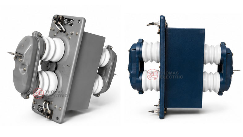
Product Display
-10 Indoor Multi-Turn Wall-Through Current Transformer Thomas Electric")
-10 Indoor Multi-Turn Wall-Through Current Transformer Thomas Electric")
Applications
- 10kV, 11kV, and 12kV indoor medium-voltage distribution systems
- Switchgear wall-through or partition-through current measurement points
- Current measurement and electric energy metering circuits
- Relay protection and differential protection circuits
- Incoming and outgoing feeder cabinets requiring insulated primary through-wall structure
- Medium-voltage switchgear where low-to-medium current ratios require a multi-turn primary CT design
Technical Features
- Multi-turn wall-through design: Compared with single-turn through-type CTs, the multi-turn structure is suitable for lower primary current ratios such as 30A to 400A.
- Porcelain-insulated primary structure: The porcelain insulation supports indoor medium-voltage insulation coordination and helps maintain clearance in cabinet wall-through applications.
- Two current-range groups: The product data separates 30–150A and 200–400A groups, with different 10% multiple values for protection-related performance selection.
- Measurement and protection outputs: The CT provides class 0.5 measurement output and class B protection-related output according to the supplied technical data.
- Differential protection option: LFC(D)-10 is used when the protection system requires differential current input.
- Panel-mounted structure: The mounting plate design supports direct installation on switchgear wall panels or partition structures.
Operating Principle
The LFC-10 / LFC(D)-10 current transformer operates according to electromagnetic induction. The primary conductor is arranged as a multi-turn through-wall structure. When current flows through the primary winding, magnetic flux is generated in the core, and the secondary winding outputs a proportional 5A signal for measuring instruments, meters, protection relays, or differential protection devices.
For measurement circuits, the CT should maintain stable ratio accuracy under the connected burden. For protection and differential protection circuits, the output must remain dependable under fault-current conditions and coordinate with the relay setting, rated output, 10% multiple, thermal withstand current, and dynamic withstand current.
Model Designation
-10 Indoor Multi-Turn Wall-Through Current Transformer Thomas Electric")
The model designation identifies the current transformer type, insulation method, wall-through structure, differential protection option, and voltage class.
| Code | Meaning |
|---|---|
| L | Current transformer |
| F | Multi-turn type |
| C | Porcelain-insulated type |
| (D) | Differential protection configuration |
| 10 | Voltage class identification; suitable for 10kV systems and IEC 12kV-class insulation coordination for 10kV, 11kV, and 12kV projects |
Technical Data
| Item | Specification |
|---|---|
| Rated voltage class | 10kV / 11kV / 12kV medium-voltage systems |
| Rated insulation level | 12/42/75kV reference; 10/42/75kV can be used according to original project specification |
| Rated frequency | 50Hz standard; 60Hz available according to project requirement |
| Rated primary current | 30A, 50A, 75A, 100A, 150A, 200A, 300A, 400A |
| Rated secondary current | 5A |
| Rated output | 10VA for accuracy class 0.5; 15VA for class B / protection reference |
| Accuracy class | 0.5 for measurement; class B / protection configuration according to project requirement |
| Rated short-time thermal current | 75 × I1n reference |
| Rated dynamic current | 2.5 × Ith reference |
| 10% multiple | 10 for 30–150A group; 15 for 200–400A group |
| Installation method | Indoor wall-through / panel-through installation |
| Applicable standard | IEC 61869-1 / IEC 61869-2; IEC 60044-1 can be referenced for legacy specification |
Selection Table
| Rated
Primary Current (A) |
Rated
Secondary Current (A) |
Rated
Output: 0.5 (VA) |
Rated
Output: B (VA) |
Rated
Insulation Level (kV) |
Short-Time
Thermal Current |
Rated
Dynamic Current |
10%
Multiple |
|---|---|---|---|---|---|---|---|
| 30, 50, 75, 100, 150 | 5 | 10 | 15 | 12/42/75 reference | 75 × I1n | 2.5 × Ith | 10 |
| 200, 300, 400 | 5 | 10 | 15 | 12/42/75 reference | 75 × I1n | 2.5 × Ith | 15 |
Note: The selection table is based on the supplied product data and reorganized for international technical use. Final current ratio, accuracy class, rated output, insulation level, differential protection configuration, thermal current, dynamic current, and test requirements shall be confirmed according to the approved drawing, nameplate, and factory test report.
Engineering Notes
The main technical difference between LFC-10 / LFC(D)-10 and single-turn wall-through current transformers is the multi-turn primary structure. This makes the series more suitable for lower current ratios. For projects where the rated primary current is 600A or above, a single-turn wall-through CT may be more suitable. For lower primary currents between 30A and 400A, the multi-turn LFC structure provides a practical solution for wall-through switchgear applications.
The 10% multiple value is also separated by current range. The 30–150A group uses a reference multiple of 10, while the 200–400A group uses a reference multiple of 15. This should be considered when selecting CTs for relay protection or differential protection circuits.
Service Conditions
- Installation location: indoor medium-voltage switchgear or wall-through cabinet structure
- System voltage: 10kV, 11kV, or 12kV class
- Rated frequency: 50Hz / 60Hz according to project requirement
- Rated insulation level: 12/42/75kV reference for IEC-style applications
- Installation form: wall-through / partition-through mounting
- The installation environment should be free from severe pollution, corrosive gas, explosive medium, heavy conductive dust, and abnormal condensation.
- For high altitude, high humidity, coastal, high-pollution, or special switchgear applications, technical confirmation is recommended before ordering.
Standards and Compliance
The LFC-10 / LFC(D)-10 current transformer can be supplied according to IEC 61869-1 and IEC 61869-2. IEC 60044-1 may be referenced for legacy project specifications. Routine tests, dielectric tests, polarity verification, ratio test, accuracy test, insulation resistance, and partial discharge requirements should be confirmed according to the final technical agreement.
Installation and Dimensions
-10 Indoor Multi-Turn Wall-Through Current Transformer Thomas Electric")
The LFC-10 / LFC(D)-10 series is designed for indoor wall-through installation. The mounting plate, porcelain-insulated primary through structure, secondary terminal area, installation holes, and wall-opening position shall be confirmed according to the approved outline drawing before switchgear design or production.
Outline Data
| Item | Reference Dimension / Note |
|---|---|
| Overall vertical reference | Approx. 700mm according to provided drawing |
| Mounting plate reference | Approx. 488mm × 212mm overall plate reference |
| Main mounting width reference | Approx. 445 ± 0.5mm |
| Central opening reference | Approx. 242mm / 291mm reference layout according to drawing |
| Mounting holes | 4 × φ15 reference, with M8 auxiliary fixing position shown in drawing |
| Drawing confirmation | Final outline, wall opening, mounting plate size, terminal position, and clearance shall be confirmed before production |
Safety Notes
- Confirm the model, voltage class, current ratio, secondary current, accuracy class, burden, insulation level, and differential protection requirement before installation.
- Check wall opening, mounting plate dimensions, porcelain insulation clearance, secondary terminal access, and grounding arrangement against the approved drawing.
- Connect primary and secondary circuits according to the project wiring diagram.
- The secondary circuit of a current transformer must not be left open when the primary circuit is energized.
- During meter or relay maintenance, short-circuit the CT secondary circuit before disconnecting any secondary wiring.
- Installation and maintenance shall be performed by qualified medium-voltage electrical personnel.
Ordering Info
Please provide the following information when requesting a quotation:
- Product model: LFC-10 or LFC(D)-10
- System voltage: 10kV, 11kV, or 12kV
- Application requirement: measurement, metering, relay protection, or differential protection
- Rated primary current: 30A, 50A, 75A, 100A, 150A, 200A, 300A, 400A, or project-specific value
- Rated secondary current: 5A
- Accuracy class and rated output requirement
- Wall-through layout, mounting plate requirement, and wall opening dimensions
- Primary conductor direction, terminal layout, and required outline drawing
- Quantity, labeling, certificates, routine test reports, and packaging requirements
Selection Tips
- Confirm installation type: Select this model when the primary conductor must pass through a switchgear wall or cabinet partition.
- Confirm current range: LFC-10 is suitable for lower current ratios such as 30A to 400A because of its multi-turn primary structure.
- Select the correct version: Use LFC-10 for measurement or standard protection circuits, and LFC(D)-10 where differential protection is required.
- Check voltage level: For international projects, confirm 12kV-class insulation coordination for 10kV, 11kV, or 12kV applications.
- Check wall-opening dimensions: Verify mounting plate size, hole spacing, primary conductor length, and secondary terminal position before cabinet production.
- Confirm protection parameters: For relay protection, confirm 10% multiple, rated output, and connected burden before final selection.