Product Overview
The LMZBJ17-12 / LMZBJ17-12Q / 170 current transformer is an indoor single-phase epoxy cast-resin cable/busbar-through current transformer for medium-voltage switchgear. It is designed for current measurement, electric energy metering, feeder monitoring, and relay protection in AC power systems with rated frequency of 50Hz or 60Hz. For international project documentation, this product can be positioned for 10kV, 11kV and 12kV class indoor switchgear applications, subject to final insulation coordination, system design, and project requirements.
This unified page combines the technical information of LMZBJ17-12Q / 170 and LMZBJ17-12Q/L into one product. Both belong to the same indoor epoxy cast-resin current transformer platform, using a large hollow aperture for cable, copper bar, or busbar-through installation. The difference is mainly in the installation dimension, aperture arrangement, and L-dimension / mounting structure reference, while the electrical selection logic remains similar: 1A or 5A secondary output, 12/42/75kV insulation level, and metering/protection accuracy combinations according to project requirements.
The transformer body is fully enclosed with epoxy resin. The primary conductor passes through the central opening, while the magnetic core and secondary windings are encapsulated inside the resin body. This structure is suitable for high-current feeder circuits, incoming panels, busbar metering, and protection circuits where reliable insulation, stable secondary output, and compact indoor installation are required.
Product Type
| Item | Specification |
|---|---|
| Product name | Indoor Epoxy Cast-Resin Cable/Busbar-Through Current Transformer |
| Model series | LMZBJ17-12 / LMZBJ17-12Q / 170 |
| Variant references | LMZBJ17-12Q / 170 and LMZBJ17-12Q/L |
| Structure | Fully enclosed epoxy cast-resin body with large hollow through-window aperture |
| Voltage class | 10kV, 11kV and 12kV class indoor medium-voltage systems |
| Rated insulation level | 12/42/75kV |
| Rated frequency | 50Hz / 60Hz |
| Rated secondary current | 5A or 1A |
| Rated primary current | 1500A, 2000A, 3000A, 4000A, 5000A |
| Applicable standards | GB20840.1-2010, GB20840.2-2014, IEC61869-2:2003, and customer-specific requirements |
Product Display
/170 Epoxy Cast-Resin Cable/Busbar-Through Current Transformer Thomas Electric")
/170 Epoxy Cast-Resin Cable/Busbar-Through Current Transformer Thomas Electric")
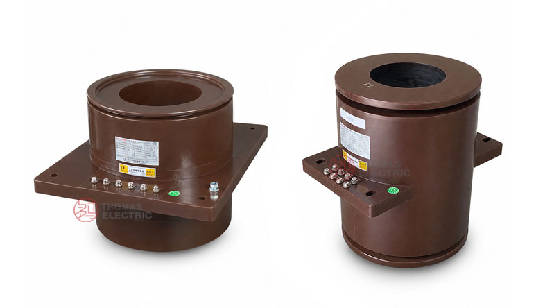
The LMZBJ17-12 series has a cylindrical cast-resin body, a square mounting base, a large center aperture, and secondary terminal blocks arranged on the front side. The primary cable or busbar passes through the aperture, while secondary terminals connect to meters, protection relays, monitoring devices, or automation systems.
Applications
- 10kV, 11kV and 12kV class indoor medium-voltage switchgear
- High-current feeder cabinets, incoming cabinets, outgoing panels, and metering cabinets
- Current measurement and electric energy metering circuits
- Relay protection circuits requiring 5P10, 5P15, 5P20, 5P25, or 5P30 protection performance
- Cable-through or busbar-through current sensing in indoor distribution systems
- Industrial substations, commercial distribution rooms, utility projects, and OEM switchgear assemblies
Features
- Unified 170-type platform: LMZBJ17-12Q / 170 and LMZBJ17-12Q/L are treated as one product family for website content and product selection.
- Large hollow aperture: The through-window design allows cable, copper bar, or busbar installation for high-current circuits.
- Fully enclosed epoxy resin casting: The cast body supports insulation strength, mechanical stability, and reliable indoor service.
- 5A and 1A secondary options: The product supports conventional 5A secondary circuits and 1A systems for lower burden or longer secondary wiring.
- High-current range: Rated primary current options cover 1500A to 5000A for large feeder and busbar applications.
- Metering and protection combinations: The product supports 0.2S / 0.5 metering cores and 5P10 to 5P30 protection core combinations.
- Dimension variants: The Q/170 and Q/L variants provide different outline references and L-dimension options for switchgear layout adaptation.
Principle
The LMZBJ17-12 current transformer operates according to electromagnetic induction. The primary cable, copper bar, or busbar passes through the central aperture and carries the primary current. The current generates magnetic flux in the internal core, and the secondary winding induces a proportional 5A or 1A signal for connected meters, protection relays, or monitoring devices.
For metering use, the CT must maintain ratio and phase accuracy under the selected burden. For protection use, the 5P-class protection core must provide a dependable current signal under fault-current conditions. Correct selection of secondary current, accuracy combination, rated output, and burden is essential for accurate measurement and reliable protection operation.
Model Designation
| Code | Meaning |
|---|---|
| L | Current transformer |
| M | Busbar / cable-through structure |
| Z | Epoxy resin casting insulation |
| B | Protection-class configuration available |
| J | Enhanced / reinforced structure series |
| 17 | Design sequence code |
| 12 | Rated voltage class: 12kV |
| Q | Reinforced type / structural variant |
| 170 / L | Aperture or installation dimension reference used for variant selection |
Technical Data
| Item | Specification |
|---|---|
| Rated voltage class | 12kV class; suitable for 10kV, 11kV and 12kV class indoor systems by project confirmation |
| Rated insulation level | 12/42/75kV |
| Rated frequency | 50Hz / 60Hz |
| Rated secondary current | 5A or 1A |
| Rated primary current | 1500A, 2000A, 3000A, 4000A, 5000A |
| Accuracy class | 0.2S, 0.5, 5P10, 5P15, 5P20, 5P25, 5P30 |
| Rated output | 10VA to 75VA depending on ratio, secondary current, and accuracy combination |
| Ambient temperature | -25°C to +40°C |
| Installation type | Indoor cable/busbar-through mounting in medium-voltage switchgear |
| Standard reference | GB20840.1-2010, GB20840.2-2014, IEC61869-2:2003, and project requirements |
Selection Table
The following selection data combines the 5A and 1A secondary current configurations shown in the catalogue. Long accuracy and output cells are split into multiple lines for better website readability.
| Rated
Current Ratio (A) |
Accuracy
Class Combination |
Rated
Output (VA) |
Secondary
Current |
|---|---|---|---|
| 1500/5 | 0.2S / 0.5 / 5P15 / 5P15 0.2S / 0.5 / 5P20 / 5P20 0.2S / 0.5 / 5P25 / 5P25 |
15/20/40/40 15/20/30/30 15/20/15/15 |
5A |
| 2000/5 | 0.2S / 0.5 / 5P15 / 5P15 0.2S / 0.5 / 5P20 / 5P20 0.2S / 0.5 / 5P25 / 5P25 |
15/20/50/50 15/20/30/30 15/20/20/20 |
|
| 3000/5 | 0.2S / 0.5 / 5P15 / 5P15 0.2S / 0.5 / 5P20 / 5P20 0.2S / 0.5 / 5P25 / 5P25 0.2S / 0.5 / 5P30 / 5P30 |
20/30/50/50 20/30/30/30 20/30/20/20 20/30/15/15 |
|
| 4000/5 | 0.2S / 0.5 / 5P15 / 5P15 0.2S / 0.5 / 5P20 / 5P20 0.2S / 0.5 / 5P25 / 5P25 0.2S / 0.5 / 5P30 / 5P30 |
30/40/50/50 30/40/30/30 30/40/20/20 30/40/10/10 |
|
| 5000/5 | 0.2S / 0.5 / 5P15 / 5P15 0.2S / 0.5 / 5P20 / 5P20 0.2S / 0.5 / 5P25 / 5P25 0.2S / 0.5 / 5P30 / 5P30 |
30/40/60/60 30/40/30/30 30/40/20/20 30/40/10/10 |
|
| 1500/1 | 0.2S / 0.5 / 5P10 / 5P10 0.2S / 0.5 / 5P15 / 5P15 0.2S / 0.5 / 5P20 / 5P20 |
10/15/40/40 10/15/25/25 10/15/15/15 |
1A |
| 2000/1 | 0.2S / 0.5 / 5P10 / 5P10 0.2S / 0.5 / 5P15 / 5P15 0.2S / 0.5 / 5P20 / 5P20 |
10/15/50/50 10/15/30/30 10/15/20/20 |
|
| 3000/1 | 0.2S / 0.5 / 5P10 / 5P10 0.2S / 0.5 / 5P15 / 5P15 0.2S / 0.5 / 5P20 / 5P20 |
10/15/50/50 10/15/30/30 10/15/15/15 |
|
| 4000/1 | 0.2S / 0.5 / 5P10 / 5P10 0.2S / 0.5 / 5P15 / 5P15 |
15/20/50/50 15/20/30/30 |
|
| 5000/1 | 0.2S / 0.5 / 5P20 / 5P20 | 10/10/15/15 |
Note: If project requirements exceed the listed range, final parameters can be determined by technical agreement between manufacturer and purchaser.
Variant Dimensions
| Variant | Dimension
Reference |
Application
Note |
|---|---|---|
| LMZBJ17-12Q / 170 | Large aperture reference with front terminal layout and square mounting base | Used for cable/busbar-through applications requiring the 170-type opening and high-current primary conductor clearance. |
| LMZBJ17-12Q/L | L-dimension option, including OTC.300.1076.1: 230 and OTC.300.1076.2: 270 reference | Used when switchgear layout requires a specific axial length or mounting depth. |
| Common outline references | Overall length, mounting plate, 4-Ø14 mounting holes, terminal area and aperture size according to approved drawing | Final dimensions must be confirmed before cabinet production. |
Service Conditions
- Installation location: indoor medium-voltage switchgear
- Rated voltage: 10kV, 11kV and 12kV class systems by project confirmation
- Rated frequency: 50Hz / 60Hz
- Ambient temperature: -25°C to +40°C
- The installation environment should be free from severe vibration, corrosive gas, explosive medium, conductive dust, heavy pollution, and abnormal condensation.
- For high altitude, coastal, humid, or heavy-pollution service conditions, technical confirmation is recommended before ordering.
Standards and Compliance
The LMZBJ17-12 series current transformer is designed according to GB20840.1-2010, GB20840.2-2014, IEC61869-2:2003, and customer-specific requirements. Routine project documentation may include ratio test, polarity verification, accuracy test, insulation test, and power-frequency withstand test according to the agreed standard.
Installation and Dimensions
/170 Epoxy Cast-Resin Cable/Busbar-Through Current Transformer Thomas Electric")
This product is installed in indoor switchgear with the cable or busbar passing through the central aperture. Before cabinet production, the opening size, mounting plate dimensions, conductor path, phase clearance, creepage distance, terminal direction, and secondary wiring access must be confirmed with the approved drawing. When selecting between Q/170 and Q/L versions, the mechanical installation depth and conductor arrangement should be checked together with the electrical specifications.
Safety Notes
- Confirm ratio, secondary current, accuracy combination, rated output, and aperture size before production.
- Check that the cable, copper bar, or busbar can pass through the aperture with sufficient clearance.
- Verify mounting hole positions, installation clearance, terminal direction, and secondary wiring space.
- The CT secondary circuit must not be open-circuited while primary current is flowing.
- Before disconnecting meters or relays, short-circuit the secondary circuit with an approved shorting device.
- One point of the secondary circuit should be grounded according to the project electrical safety practice.
- Installation and commissioning shall be performed by qualified medium-voltage electrical personnel.
Ordering Info
- Product model: LMZBJ17-12 / LMZBJ17-12Q / 170
- Variant requirement: Q/170 or Q/L
- Rated primary current and rated secondary current: 5A or 1A
- Accuracy class combination and rated output for each secondary core
- Required protection class: 5P10, 5P15, 5P20, 5P25, 5P30, or project-specific requirement
- Cable or busbar size and aperture requirement
- Mounting drawing, terminal direction, and switchgear layout
- Applicable standard, routine test report, and certificate requirements
- Quantity, label language, packaging, and project documentation requirements
Selection Guide
- Confirm voltage class: Use this product for indoor 10kV, 11kV and 12kV class switchgear after insulation coordination is confirmed.
- Select current ratio: Choose 1500A to 5000A according to feeder current, busbar capacity, and protection setting.
- Select secondary current: Use 5A for conventional secondary circuits or 1A where lower burden or longer wiring distance is required.
- Check aperture and depth: Confirm the cable, copper bar, or busbar can pass through the aperture and that the Q/170 or Q/L dimensions match the switchgear layout.
- Define cores: Use 0.2S / 0.5 for metering and 5P classes for protection according to the relay scheme.
- Verify rated output: Ensure the connected meter, relay, and cable burdens do not exceed the selected rated output.
- Approve drawings: Confirm aperture, mounting holes, terminal layout, and base dimensions before cabinet production.