Product Overview
The LQJ(C)-10 current transformer is an indoor semi-enclosed epoxy resin cast current transformer designed for medium-voltage power systems. It is suitable for IEC-oriented 10kV, 11kV, and 12kV switchgear applications and is used for current measurement, electric energy metering, feeder monitoring, relay protection, and differential protection in AC systems with rated frequency of 50Hz or 60Hz.
The product uses epoxy resin as the main insulation system. The primary winding and part of the secondary winding are cast into one resin body, while the other part of the secondary winding and the ring core are exposed or semi-enclosed according to the product structure. The primary lead-out terminals are arranged on the top, and the secondary terminal block is arranged on the side, making the product suitable for compact indoor switchgear layouts and maintenance-oriented wiring access.
Product Type
| Item | Specification |
|---|---|
| Product name | Indoor Semi-Enclosed Epoxy Resin Cast Current Transformer |
| Model series | LQJ(C)-10 |
| Product structure | Indoor single-phase, coiled-type, semi-enclosed epoxy resin cast current transformer |
| Voltage class | 10kV, 11kV, and 12kV medium-voltage systems |
| Highest voltage for equipment | 12kV class |
| Rated insulation level | 12/42/75kV reference insulation level for 12kV-class systems |
| Rated frequency | 50Hz / 60Hz |
| Rated secondary current | 5A or 1A according to project requirement |
| Application type | Current measurement, energy metering, relay protection, differential protection, and switchgear monitoring |
| Installation location | Indoor medium-voltage switchgear, metering cabinets, and distribution equipment |
| Applicable standard | IEC 61869-1 / IEC 61869-2; IEC 60044-1 can be referenced for legacy projects |
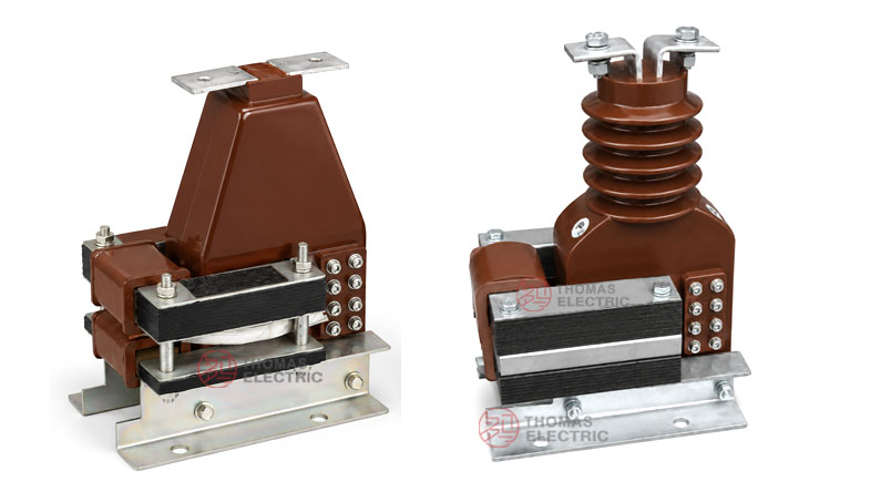
Product Display
-10 Semi-Enclosed Epoxy Resin Cast Current Transformer, 10kV–12kV Thomas Electric")
-10 Semi-Enclosed Epoxy Resin Cast Current Transformer, 10kV–12kV Thomas Electric")
Main Applications
- 10kV, 11kV, and 12kV indoor medium-voltage distribution systems
- Air-insulated switchgear, metering cabinets, feeder panels, and circuit breaker cabinets
- Current measurement and electric energy metering circuits
- Relay protection and differential protection circuits
- Industrial substations, utility distribution rooms, and commercial power systems
- Indoor switchgear applications requiring top primary terminals and side secondary terminal access
Key Technical Features
- International voltage-class application: Suitable for 10kV, 11kV, and 12kV systems with IEC-style 12/42/75kV insulation coordination.
- Semi-enclosed epoxy resin structure: The primary winding and part of the secondary winding are cast into one resin body, while the exposed secondary and ring core arrangement supports the semi-enclosed product structure.
- Coiled-type primary design: The coiled primary structure is suitable for lower primary current ratios and accurate current transformation.
- Differential protection option: The C-type model code is used for differential protection applications where the protection circuit requires differential current signal input.
- Accessible wiring layout: Primary terminals are arranged on the top and secondary terminals are placed on the side for convenient switchgear wiring.
- Standard and customized ratios: Standard current ratios are available, and special ratios, burdens, secondary currents, and terminal arrangements can be confirmed by technical agreement.
Working Principle
The LQJ(C)-10 current transformer operates according to electromagnetic induction. Primary current flowing through the coiled primary winding generates magnetic flux in the ring core, and the secondary winding outputs a proportional current signal to connected meters, relays, or monitoring devices. The epoxy resin cast body provides insulation between the medium-voltage primary circuit and the low-voltage secondary circuit.
For metering circuits, the CT should maintain the required ratio accuracy and phase displacement within the rated burden. For protection and differential protection circuits, the secondary winding should provide a reliable current signal under fault-current conditions and coordinate with relay settings, rated burden, and system short-circuit requirements.
Model Designation
-10 Semi-Enclosed Epoxy Resin Cast Current Transformer, 10kV–12kV Thomas Electric")
The model designation identifies the product type, coiled winding structure, enhanced capacity, differential protection configuration, and voltage class.
| Code | Meaning |
|---|---|
| L | Current transformer |
| Q | Coiled type / coil-wound primary structure |
| J | Enlarged capacity / enhanced secondary output configuration |
| C | Differential protection configuration |
| 10 | Voltage class identification; applicable to 10kV systems and IEC 12kV-class insulation coordination for 10kV, 11kV, and 12kV projects |
Model example: LQJ(C)-10 indicates an indoor coiled-type current transformer with enlarged capacity and differential protection configuration, specified for 10kV-class systems and suitable for 12kV-class insulation coordination when required by the project.
Technical Data
| Item | Specification |
|---|---|
| Rated voltage class | 10kV / 11kV / 12kV medium-voltage systems |
| Highest voltage for equipment | 12kV class |
| Rated insulation level | 12/42/75kV reference |
| Rated frequency | 50Hz / 60Hz |
| Rated primary current | 5A to 600A reference range; customized ratios available according to project requirement |
| Rated secondary current | 5A or 1A |
| Accuracy class combination | 0.2 / 0.5, 0.5 / 0.5, 0.2 / 10P, 0.5 / 10P or project-specific measuring / protection combinations |
| Rated output | 10VA / 15VA / 20VA or project-specific burden according to secondary core configuration |
| Protection type | Relay protection and differential protection configurations available |
| Partial discharge test | Available according to IEC 61869 project requirement |
| Insulation medium | Epoxy resin casting insulation |
| Installation method | Indoor mounting according to approved drawing |
| Applicable standard | IEC 61869-1 / IEC 61869-2; IEC 60044-1 can be referenced for legacy specification |
Windings & Terminal Marking
The LQJ(C)-10 current transformer can be supplied with measuring, metering, protection, or differential protection secondary winding configurations. The primary lead-out terminals are arranged on the top, while the secondary terminal block is located on the side of the product structure.
| Terminal Marking | Function | Application Note |
|---|---|---|
| P1 / P2 | Primary terminals | Top primary lead-out terminals. The reference primary current direction is normally defined from P1 to P2. |
| 1S1 / 1S2 | First secondary winding | Usually used for measurement, metering, or the first specified secondary core. |
| 2S1 / 2S2 | Second secondary winding | Usually used for relay protection, differential protection, or an additional secondary circuit when required. |
| Side terminal block | Secondary wiring interface | Secondary terminals are arranged on the side for wiring access and maintenance. |
Terminal markings follow standard CT polarity conventions. Correct terminal identification shall be observed to ensure metering accuracy, relay direction judgment, and protection performance. The secondary circuit must not be open-circuited when the primary circuit is energized.
DATA Reference
| Rated
Primary Current (A) |
Accuracy
Class Combination |
Rated
Secondary Current (A) |
Rated
Output (VA) |
Application
Note |
|---|---|---|---|---|
| 5–50 | 0.2 / 0.5 0.5 / 0.5 0.2 / 10P 0.5 / 10P |
5 or 1 | 10 / 15 | Low-current measurement and metering applications |
| 75–100 | 10 / 15 | Measurement, metering, and feeder monitoring circuits | ||
| 150–200 | 10 / 15 | Standard protection and metering applications | ||
| 300–400 | 15 / 15 | Medium-current feeder or differential protection applications | ||
| 500–600 | 15 / 20 | Higher current feeder or customized protection applications |
Note: The table is for preliminary engineering selection. Final current ratio, secondary current, accuracy class, rated output, thermal current, dynamic current, insulation level, partial discharge requirement, and terminal arrangement shall be confirmed according to nameplate data, approved drawings, and factory test reports.
Service Conditions
- Installation location: indoor medium-voltage switchgear
- System voltage: 10kV, 11kV, or 12kV class
- Rated frequency: 50Hz / 60Hz
- Rated insulation level: 12/42/75kV reference
- Altitude: not over 1000m under standard service conditions unless otherwise specified
- Ambient temperature: -5°C to +40°C
- Relative humidity: less than 85% at 20°C under reference conditions
- The product can be specified for vibration-resistant switchgear applications according to project requirements.
- The installation environment should be free from severe vibration beyond specification, corrosive gas, explosive medium, heavy pollution, and abnormal condensation.
Standards and Compliance
The LQJ(C)-10 current transformer can be supplied according to IEC 61869-1 and IEC 61869-2. IEC 60044-1 may be referenced for legacy project specifications. Routine tests, dielectric tests, polarity verification, ratio test, accuracy test, insulation resistance, and partial discharge requirements should be confirmed according to the final technical agreement.
Installation and Dimensions
-10 Semi-Enclosed Epoxy Resin Cast Current Transformer, 10kV–12kV Thomas Electric")
The LQJ(C)-10 series is designed for indoor switchgear installation. The semi-enclosed body, top primary terminals, side secondary terminal block, mounting structure, terminal direction, and electrical clearances shall be confirmed according to the approved outline drawing before cabinet design or batch production.
Structure & Dimensions
| Item | Selection Note |
|---|---|
| Mechanical structure | Indoor semi-enclosed epoxy resin cast current transformer |
| Primary structure | Coiled-type primary winding according to current ratio and design configuration |
| Primary terminals | Top P1 / P2 terminal arrangement according to approved drawing |
| Secondary terminals | Side terminal block with 1S1 / 1S2 and optional 2S1 / 2S2 according to configuration |
| Drawing confirmation | Final outline, terminal direction, and mounting dimensions shall be confirmed before switchgear production |
Installation Safety Notes
- Confirm the model, voltage class, current ratio, secondary current, accuracy class, burden, insulation level, and protection requirement before installation.
- Check switchgear mounting space, top primary terminal connection, side secondary wiring access, phase clearance, grounding arrangement, and maintenance access against the approved drawing.
- Connect primary and secondary terminals according to terminal markings and the project wiring diagram.
- The secondary circuit of a current transformer must not be left open when the primary circuit is energized.
- During meter or relay maintenance, short-circuit the CT secondary circuit before disconnecting any secondary wiring.
- Secondary grounding shall follow the project specification and local electrical safety requirements.
- Installation and maintenance shall be performed by qualified medium-voltage electrical personnel.
Ordering Information
Please provide the following information when ordering or requesting a quotation:
- Product model: LQJ(C)-10
- System voltage: 10kV, 11kV, or 12kV
- Rated primary current / current transformation ratio
- Rated secondary current: 1A or 5A
- Application requirement: measurement, metering, relay protection, or differential protection
- Accuracy class combination and rated output for each secondary core
- Protection class and relay protection requirement if applicable
- Insulation level and applicable IEC standard
- Switchgear type, installation layout, terminal direction, and required outline drawing
- Quantity, labeling, certificates, routine test reports, and packaging requirements
- Special customized current ratio, secondary winding, burden, or terminal arrangement requirements
Selection Guidelines
- Confirm voltage level: Select LQJ(C)-10 for indoor 10kV, 11kV, or 12kV switchgear using 12kV-class insulation coordination.
- Confirm application type: Confirm whether the CT is used for measurement, metering, relay protection, or differential protection.
- Confirm primary current: Select the rated primary current according to feeder load, metering range, and protection setting range.
- Confirm secondary current: Use 5A or 1A according to connected meters, relays, cable length, and total burden calculation.
- Define accuracy combination: Specify measurement, metering, and protection accuracy classes according to the secondary circuit requirement.
- Check rated burden: Ensure the connected burden, including instruments and wiring, does not exceed the rated output of each secondary core.
- Confirm drawings: Verify outline dimensions, top primary terminal direction, side terminal block position, and electrical clearances before switchgear integration.
FAQs