Product Overview
The LZZB11-24/180-220 voltage transformer is an indoor epoxy cast-resin instrument transformer designed for 20kV, 22kV and 24kV medium-voltage switchgear. It is positioned for voltage sensing, metering reference and protection signal applications in indoor AC power systems with 50Hz or 60Hz rated frequency. Compared with conventional 24kV instrument transformers, this model is better described as a compact dual-layout 24kV epoxy cast-resin voltage transformer platform, with two installation layouts for different primary-side arrangement requirements.
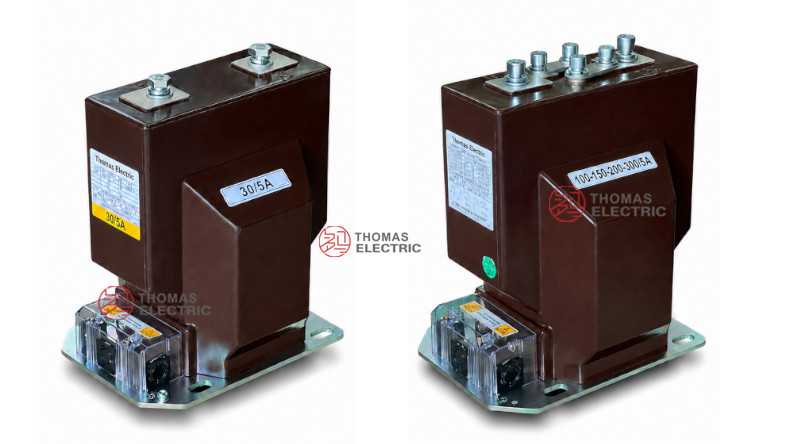
The product adopts a fully enclosed epoxy resin casting structure with a rated insulation level of 24/65/125kV. The catalogue drawing shows two installation references, including a standard layout and a 2×600A layout, which makes this page suitable for engineers who need to confirm installation space, terminal arrangement, wiring diagram and cabinet compatibility before switchgear design. The product complies with GB 20840.3-2013 and IEC 61869-3:2011, and can be used in indoor medium-voltage panels requiring stable insulation, clear terminal marking and reliable measurement output.
Product Type


| Item | Specification |
|---|---|
| Product name | Indoor Epoxy Cast-Resin Voltage Transformer |
| Model | LZZB11-24/180-220 |
| Application | Voltage measurement, metering reference and protection signal output |
| Operation condition | Indoor |
| Phase | Single-phase instrument transformer |
| Insulation medium | Epoxy resin cast insulation |
| Voltage class | 20kV, 22kV and 24kV class indoor systems |
| Rated insulation level | 24/65/125kV |
| Rated frequency | 50Hz / 60Hz |
| Installation structure | Indoor switchgear-mounted structure with standard and 2×600A layout references |
| Applicable standards | GB 20840.3-2013, IEC 61869-3:2011; project-specific requirements by agreement |
Product Positioning
This product should be differentiated from the previous 24kV current transformer pages. The key positioning is not multi-secondary CT protection output, but 24kV epoxy cast-resin voltage transformer for indoor switchgear voltage reference. Its value is in insulation coordination, compact cabinet integration, primary terminal layout, wiring diagram clarity and use in medium-voltage metering/protection voltage circuits.
| Positioning Point | Technical Meaning | Website Expression |
|---|---|---|
| Voltage transformer page | Designed for voltage signal reference instead of current conversion | 24kV indoor epoxy cast-resin voltage transformer for measurement and protection voltage circuits |
| 180-220 structure | Structure code for cabinet installation and terminal layout | Compact indoor platform with clear dimension references for switchgear integration |
| Dual installation layout | Two drawing variants shown in catalogue | Standard layout and 2×600A arrangement available by project confirmation |
| IEC 61869-3 | Voltage transformer standard reference | IEC-oriented VT documentation for international MV projects |
| Epoxy insulation | Dry-type fully cast structure | Oil-free insulation with stable dielectric performance and low maintenance |
Applications
- 20kV, 22kV and 24kV indoor medium-voltage switchgear
- Voltage measurement and metering reference circuits
- Protection relays requiring stable voltage input signals
- Utility substations, industrial distribution rooms and feeder panels
- MV switchgear systems requiring compact epoxy cast-resin instrument transformers
- Projects requiring IEC 61869-3 and GB 20840.3 documentation
- Cabinet layouts requiring confirmation of standard or 2×600A terminal arrangement
Features
- 24kV voltage transformer positioning: Developed for voltage measurement and protection voltage reference in indoor MV switchgear.
- Epoxy cast-resin insulation: Fully enclosed dry-type insulation structure supports stable dielectric performance and moisture resistance.
- 24/65/125kV insulation level: Suitable for 20kV, 22kV and 24kV class indoor equipment documentation.
- Dual installation references: Catalogue drawing includes a standard layout and a 2×600A arrangement for different cabinet designs.
- Clear wiring diagram: P1/P2 and S terminal marking supports polarity identification and correct secondary wiring.
- IEC voltage transformer standard: Technical documentation can be aligned with IEC 61869-3 and GB 20840.3 requirements.
Operating Principle
The LZZB11-24/180-220 voltage transformer converts the primary medium-voltage signal into a lower secondary voltage signal for measuring instruments, meters and protection relays. The primary winding, secondary winding and insulation system are integrated into a cast-resin body, providing electrical isolation between the high-voltage circuit and the low-voltage secondary circuit.
In operation, the secondary voltage should be connected only to the specified burden range. The wiring diagram and terminal marking must be followed to maintain correct polarity, accurate metering signal and reliable protection logic. The final transformation ratio, burden and terminal allocation should be confirmed according to the nameplate and approved wiring diagram.
Model Designation

Technical Data
| Item | Specification |
|---|---|
| Model | LZZB11-24/180-220 |
| Transformer type | Indoor epoxy cast-resin voltage transformer |
| Rated voltage class | 20kV, 22kV and 24kV indoor systems |
| Rated insulation level | 24/65/125kV |
| Rated frequency | 50Hz / 60Hz |
| Ambient temperature | -5°C to +40°C |
| Standard references | GB 20840.3-2013, IEC 61869-3:2011 |
| Insulation structure | Fully enclosed epoxy resin cast body |
| Terminal arrangement | P1 / P2 primary terminals; S1 / S2 / S3 or tapped secondary terminals according to wiring diagram |
| Installation reference | Standard layout and 2×600A layout shown in catalogue drawing |
Catalogue Rating Reference
The supplied catalogue table includes selection groups for the product platform. Because the table combines rating groups, accuracy combinations and short-time withstand references, it should be used for preliminary engineering comparison only. Final electrical data must follow the confirmed nameplate, approved drawing and factory test report.
| Reference Rating Group |
Accuracy Class Combination |
Rated Output (VA) |
Rated Short-Time Withstand Reference |
Dynamic Withstand Reference |
|---|---|---|---|---|
| 20–40 | 0.2S / 0.5 | 10 | 80 × In | 2.5 × Ith |
| 50–100 | ||||
| 150–250 | 15 | |||
| 300–600 | 15 | |||
| 10–20 15–30 20–40 30–60 40–80 100–200 150–300 200–400 300–600 |
0.2S / 0.5 | 10 / 15 | 80 × In | 2.5 × Ith |
| 100–150–200–300 150–200–300–400 200–300–400–600 |
0.2S / 0.5 | 10 / 15 | 80 × In | 2.5 × Ith |
Note: Rated output and relative accuracy class only correspond to the specified rating group. Parameters outside the catalogue range can be confirmed by technical agreement between manufacturer and purchaser.
Windings & Terminal Marking

The product drawing includes two wiring references. The standard wiring diagram uses P1 and P2 on the primary side, with S1 and S2 on the secondary side. The tapped / dual-ratio wiring reference includes C1 and C2 tap terminals and S1, S2, S3 secondary terminals. Final terminal marking must follow the approved wiring diagram and nameplate.
| Terminal | Function | Application Note |
|---|---|---|
| P1 / P2 | Primary terminals | Used for primary polarity and voltage-side connection reference. |
| S1 / S2 | Standard secondary terminals | Used for standard secondary voltage output connection. |
| S1 / S2 / S3 | Tapped secondary output terminals | Used where multiple secondary output or tap configuration is specified. |
| C1 / C2 | Primary-side tap or connection reference | Used in the tapped wiring configuration shown in the catalogue drawing. |
| Grounding point | Protective grounding | Secondary grounding shall be arranged according to project wiring rules and local electrical safety requirements. |
Service Conditions
- Installation site: indoor medium-voltage switchgear
- Rated frequency: 50Hz / 60Hz
- Ambient temperature: -5°C to +40°C
- The installation environment should be free from severe pollution, conductive dust, corrosive gas, explosive medium and heavy condensation.
- Altitude, humidity, seismic requirement and special environmental conditions should be confirmed according to project specification.
Standards and Compliance
The LZZB11-24/180-220 voltage transformer is documented according to GB 20840.3-2013 and IEC 61869-3:2011. For international projects, the product page should use IEC 61869-3 wording rather than current-transformer standard wording. Routine test, accuracy verification, power-frequency withstand test, partial discharge test and final acceptance should follow the confirmed order specification and factory test report.
Installation and Dimensions

Dimensions
| Dimension Item | Reference Value / Note |
|---|---|
| Top terminal spacing | 220mm reference |
| Base width | 230mm reference |
| Body height | Approx. 274mm reference |
| Overall height | Approx. 280mm reference |
| Base mounting layout | Four-hole base mounting structure; final hole position according to approved drawing |
| Standard layout | Reference drawing for I1n ≤ 1250A shown in catalogue |
| Special layout | Reference drawing for I1n: 2×600A shown in catalogue |
Before switchgear production, confirm the product structure code, installation layout, base mounting holes, top terminal spacing, terminal box direction, wiring diagram and maintenance access space. For the 2×600A arrangement, the primary terminal drawing should be checked separately because the busbar and tap layout differ from the standard layout.
Safety Notes
- Confirm model, rated insulation level, transformation ratio, burden, accuracy class and wiring diagram before production.
- Use only the approved terminal arrangement for the selected standard or tapped configuration.
- Check base mounting dimensions, terminal spacing and cabinet clearance before assembly.
- Secondary wiring and grounding must follow the project wiring diagram and local electrical safety regulations.
- Do not short-circuit the secondary side of a voltage transformer during normal operation.
- All installation, testing and maintenance work shall be performed by qualified medium-voltage electrical personnel.