Product Overview
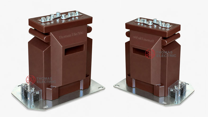
The LZZBJ12-35/210 (ATB-30-210) indoor epoxy resin cast current transformer is a compact support-type current transformer designed for 35kV / 36kV / 40.5kV medium-voltage power systems. It is used for current measurement, energy metering and relay protection in indoor AC systems with rated frequency of 50Hz or 60Hz. The product adopts a fully enclosed epoxy resin cast structure, sealing the winding and magnetic core inside the resin body to provide reliable insulation, moisture resistance and mechanical strength for switchgear applications.
This product should be positioned differently from the previous LZZBJ9-35G/220 and LZZBJ9-35/300F platforms. The LZZBJ12-35/210 is a newer compact 210mm-width CT platform with a rectangular resin body, side secondary terminal box and multiple wiring arrangements. The model is especially suitable for indoor switchgear where compact width, clear terminal access and flexible single-ratio or multi-ratio wiring are required. The catalogue also lists the export / project designation ATB-30-210, which can be used together with LZZBJ12-35/210 for international product pages.
Product Type
 Indoor Epoxy Resin Cast Current Transformer Thomas Electric")
| Item | Specification |
|---|---|
| Product name | Indoor Epoxy Resin Cast Current Transformer |
| Models | LZZBJ12-35/210 / ATB-30-210 |
| Installation condition | Indoor |
| Structure | Fully enclosed support-type / pillar-type epoxy resin cast structure |
| Structure platform | 210mm compact switchgear CT platform |
| Application | Current measurement, energy metering and relay protection |
| System voltage class | 35kV / 36kV / 40.5kV |
| Rated insulation level | 40.5/80/185kV reference from catalogue; 40.5/95/185kV may be confirmed by project standard if required |
| Rated frequency | 50Hz or 60Hz |
| Rated secondary current | 5A or 1A |
| Reference primary current range | 5A to 1000A reference range according to catalogue tables and ratio configuration |
| Typical installation | Compact indoor switchgear, metering cabinet, protection cabinet and distribution panel |
Model Explanation
 Indoor Epoxy Resin Cast Current Transformer Thomas Electric")
- L: Current transformer.
- Z: Support-type / pillar-type current transformer structure.
- Z: Epoxy resin casting insulation.
- B: Current transformer series with metering and protection winding options.
- J: Reinforced / protection-capable design reference.
- 12: Product design sequence / compact 35kV indoor CT platform code.
- 35: 35kV-class product, suitable for 35kV / 36kV / 40.5kV systems.
- 210: 210mm-class compact body width / structure platform.
Applications
- 35kV, 36kV and 40.5kV indoor medium-voltage AC systems
- Compact air-insulated switchgear and indoor distribution cabinets
- Current measurement and energy metering circuits
- Relay protection for feeder, transformer and bus-section circuits
- Projects requiring compact 210mm-width CT installation
- Switchgear panels requiring side terminal access and flexible wiring diagrams
- Single-ratio, dual-ratio and multi-secondary output current transformer applications
- Industrial substations, commercial distribution rooms and utility metering systems
Features
- Compact 210mm platform: Designed for 35kV-class switchgear where a smaller CT body and efficient cabinet layout are required.
- Fully enclosed epoxy resin casting: The active parts are sealed inside the resin body for reliable insulation and moisture resistance.
- Multiple wiring options: The catalogue provides single secondary, dual-ratio and multi-terminal wiring diagrams for different metering and protection requirements.
- Side terminal access: The secondary terminal box is located on the side / lower section for easier inspection and wiring inside the cabinet.
- Metering and protection functions: Supports 0.2S / 0.5 metering classes and 5P / 10P protection class combinations.
- Flexible primary ratio design: The selection table includes low-current ratios, standard ratios and combined ratio arrangements such as 10-15-20A or 150-200-300-400A.
- Short-time withstand capability: Catalogue data includes thermal current references such as 80 x I1n, 100 x I1n, 31.5kA and 40kA according to current range.
- Switchgear-friendly dimensions: The 210mm side-width body and 300mm base layout support compact panel installation.
Structure Overview
The LZZBJ12-35/210 adopts a compact epoxy resin cast structure with a rectangular support body. The upper part contains the primary conductor terminal area, while the lower and side sections contain the secondary terminal block and mounting structure. Compared with larger 270mm or 300F platforms, the 210mm structure is more compact and better suited for switchgear panels with limited lateral space.
The wiring diagrams show several terminal arrangements, including a basic P1/P2 primary winding with S1/S2 secondary output, dual-ratio arrangements with C1/C2 points, and multi-secondary wiring with terminals such as 1S1, 1S2, 2S1, 2S2 and 2S3. This makes the product suitable for flexible ratio configuration, metering output and protection output within one compact body.
Operating Principle
The current transformer converts the primary current in a 35kV / 36kV / 40.5kV circuit into a standardized secondary current, normally 5A or 1A. The secondary signal is connected to metering instruments, energy meters, protection relays or monitoring devices. This allows current to be measured safely while isolating the secondary circuit from the high-voltage primary system.
For metering applications, the CT must maintain ratio accuracy and phase displacement within the selected class and rated burden. For protection applications, the protection winding must provide reliable output under fault-current conditions. Therefore, current ratio, accuracy class, rated output, short-time thermal current and dynamic current should be selected according to system load, relay setting, cable burden and switchgear fault level.
Technical Data
| Parameter | Specification |
|---|---|
| Models | LZZBJ12-35/210 / ATB-30-210 |
| Product type | Indoor epoxy resin cast current transformer |
| System voltage class | 35kV / 36kV / 40.5kV |
| Rated insulation level | 40.5/80/185kV catalogue reference; 40.5/95/185kV can be confirmed by project standard where required |
| Rated frequency | 50Hz or 60Hz |
| Rated secondary current | 5A or 1A |
| Reference primary current range | 5A to 1000A according to catalogue tables and ratio arrangement |
| Accuracy classes | 0.2S, 0.2, 0.5, 10P5, 5P5, 10P10, 5P10, 10P20 and related combinations |
| Rated output | 5VA, 7.5VA, 10VA, 15VA and project-specific combinations according to accuracy class |
| Rated short-time thermal current | 80 x I1n, 100 x I1n, 31.5kA or 40kA reference according to current range |
| Rated dynamic current | 2.5 x Ith reference or 80kA / 100kA according to current range |
| Ambient temperature | -5°C to +40°C |
| Applicable standards | IEC 61869-1, IEC 61869-2, GB/T 20840.1, GB/T 20840.2; legacy IEC 61869-2:2012 and GB20840.2-2014 references by agreement |
Selection Table
The following selection table is reorganized from the supplied catalogue information for website display. Final parameters shall follow the approved drawing, nameplate and factory test report.
| Current Ratio Range |
Accuracy Class Combination |
Rated Output (VA) |
Short-Time Thermal Current |
Dynamic Current |
|---|---|---|---|---|
| 50-1000A | 0.2S / 0.5 0.2S / 10P10 0.5 / 10P10 0.2S / 10P15 0.5 / 10P20 |
15 / 15 / 10 / 7.5 | 80 x I1n to 40kA | 2.5 x Ith to 100kA |
| 10-360A combined ratios | 0.2S / 0.5 0.2S / 10P10 0.5 / 10P15 0.2S / 10P20 |
15 / 15 / 15 / 10 | 80 x I1n or 100 x I1n | 2.5 x Ith |
| 10-15-20A to 300-400A | 0.2 / 0.5 0.2S / 10P10 0.5 / 10P10 0.5 / 10P20 |
10 / 15 / 10 / 7.5 | 80 x I1n reference | 2.5 x Ith reference |
Note: Rated output and accuracy class must be selected as a matched combination. Parameters beyond the catalogue range can be confirmed by technical agreement between manufacturer and purchaser.
Operating Conditions
- Installation: Indoor installation for 35kV / 36kV / 40.5kV switchgear and distribution systems.
- Rated frequency: 50Hz or 60Hz.
- Ambient temperature: -5°C to +40°C.
- Site condition: No severe vibration, shock or mechanical impact at the installation site.
- Air quality: Ambient air should not be seriously polluted by dust, smoke, corrosive gases, vapours or salt.
- Humidity: Indoor service without severe condensation; special requirements should be confirmed by project agreement.
- Maintenance: Keep the epoxy resin surface clean and dry to maintain insulation performance.
- Wiring check: Confirm the correct wiring diagram, ratio connection and terminal marking before energizing.
Installation and Dimensions
 Indoor Epoxy Resin Cast Current Transformer Thomas Electric")
The LZZBJ12-35/210 is designed for compact indoor switchgear installation. The supplied drawing shows a side width of approximately 210mm, an overall height of approximately 340mm, a front base width of approximately 255mm, and a bottom mounting layout of approximately 300mm. The product also provides different primary terminal and wiring layouts according to the selected ratio arrangement. Final dimensions must follow the approved project drawing.
| Installation Item | Recommended Check Point |
|---|---|
| Switchgear space | Confirm 210mm side width, overall height, base width and side terminal access. |
| Primary terminal layout | Check whether basic, dual-ratio or multi-terminal primary wiring is required. |
| Primary polarity | Confirm P1 / P2 direction and conductor connection before installation. |
| Secondary terminal area | Reserve enough side access for wiring, testing and inspection. |
| Mounting base | Confirm fixing hole arrangement, base support and grounding position. |
| Electrical clearance | Confirm phase-to-ground and phase-to-phase clearance for 40.5kV equipment class. |
| Drawing confirmation | Use the approved outline drawing and wiring diagram for final production. |
Windings & Terminal Marking
The primary terminals are identified as P1 and P2. Some configurations may include primary ratio terminals such as C1 and C2. Secondary terminals may be marked as S1 / S2 for single secondary output, or 1S1 / 1S2, 2S1 / 2S2, 2S3 for multi-secondary and dual-ratio configurations.
| Terminal | Function | Application Note |
|---|---|---|
| P1 / P2 | Primary terminals | Primary current direction and polarity reference. |
| C1 / C2 | Primary ratio connection points | Used for dual-ratio or special primary connection where applicable. |
| S1 / S2 | Single secondary winding | Used for basic measurement or protection output. |
| 1S1 / 1S2 | First secondary winding | Usually assigned to metering or measurement circuit. |
| 2S1 / 2S2 / 2S3 | Second secondary winding / ratio output | Used for protection or dual-ratio secondary output according to wiring diagram. |
| Grounding point | Secondary circuit grounding reference | One point of the secondary circuit should be grounded according to project practice. |
Wiring Diagram Reference
| Wiring Type | Terminal Arrangement | Application Note |
|---|---|---|
| Single-ratio wiring | P1 / P2 with S1 / S2 | Basic CT output for one measurement or protection circuit. |
| Dual-ratio primary wiring | P1 / C1 / C2 / P2 with S1 / S2 | Used where ratio selection is realized through primary terminal connection. |
| Two-secondary wiring | 1S1 / 1S2 and 2S1 / 2S2 | Allows separate measurement and protection outputs. |
| Multi-terminal secondary wiring | 1S1 / 1S2 / 1S3 and 2S1 / 2S2 / 2S3 | Used for multi-ratio or multi-core secondary output according to the approved diagram. |
Standards and Compliance
For international product pages, the LZZBJ12-35/210 / ATB-30-210 should be specified according to IEC 61869-1 and IEC 61869-2. GB-based documentation can refer to GB/T 20840.1 and GB/T 20840.2. Legacy catalogue references such as IEC 61869-2:2012 and GB20840.2-2014 may be retained for tender compatibility, but modern technical pages should use IEC 61869 and GB/T 20840 series as the preferred standard language.