Product Overview
The LZZBJ9-10C1 / LZZBJ9-10C2 and LZZBJ9-12C1 / LZZBJ9-12C2 current transformer is an indoor, single-phase, epoxy resin cast, fully enclosed post-type current transformer designed for medium-voltage power distribution systems. It is suitable for 10kV, 11kV, and 12kV switchgear applications and is used for current measurement, energy metering, feeder monitoring, and relay protection in AC electrical systems with rated frequency of 50Hz or 60Hz.
The product encloses the primary winding, secondary winding, and annular magnetic core inside an epoxy resin casting body. This structure provides insulation strength, mechanical support, moisture resistance, and compact installation performance for indoor switchgear. The C1 and C2 versions are mechanical and application variants under the LZZBJ9 platform, selected according to switchgear layout, voltage class, current ratio arrangement, secondary core configuration, and terminal direction.
Product Type
| Item | Specification |
|---|---|
| Product name | Epoxy Resin Cast Fully Enclosed Post-Type Current Transformer |
| Model series | LZZBJ9-10C1 / LZZBJ9-10C2 / LZZBJ9-12C1 / LZZBJ9-12C2 |
| Product structure | Indoor single-phase, fully enclosed, epoxy resin cast, post-type current transformer |
| Voltage class | 10kV, 11kV, and 12kV medium-voltage systems |
| Rated insulation level | 12/28/75kV or 12/42/75kV according to project requirement |
| Rated frequency | 50Hz / 60Hz |
| Rated secondary current | 5A or 1A according to order requirement |
| Ratio configuration | Single ratio or double ratio configuration available according to variant and project specification |
| Installation location | Indoor switchgear and medium-voltage distribution equipment |
| Applicable standard | IEC 60044-1; IEC 61869-1 and IEC 61869-2 can be applied according to project requirement |
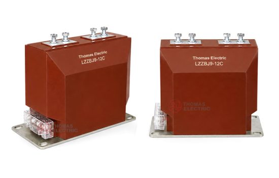
Product Display


Main Applications
- 10kV, 11kV, and 12kV indoor medium-voltage power distribution systems
- Medium-voltage switchgear, feeder panels, and circuit breaker cabinets
- Current measurement and industrial energy metering circuits
- Relay protection systems for feeders, transformers, motors, and distribution lines
- Electrical monitoring, SCADA, and power management systems
- Switchgear assemblies requiring compact post-type CT installation and stable secondary signal output
Key Technical Features
- 10kV–12kV voltage class coverage: The same product platform can be specified for 10kV, 11kV, or 12kV indoor switchgear projects according to insulation coordination and project requirements.
- Fully enclosed epoxy resin casting: The primary winding, secondary winding, and annular core are encapsulated in epoxy resin to improve insulation stability, moisture resistance, and mechanical strength.
- Post-type support structure: The product provides both current transformation and mechanical support functions inside medium-voltage switchgear.
- C1 and C2 mechanical variants: C1 and C2 provide different installation and structural arrangements for different switchgear layouts and ratio configurations.
- Single ratio and double ratio options: The series supports single-ratio and double-ratio selection, allowing adaptation to different feeder current ranges and metering/protection requirements.
- Metering and protection cores: Available accuracy combinations include metering classes such as 0.2S / 0.5 and protection classes such as 10P according to project configuration.
- Short-circuit withstand capability: Short-time thermal current and dynamic current ratings are selected according to the rated current ratio and switchgear fault-current level.
Working Principle
The LZZBJ9-10C1 / LZZBJ9-10C2 / LZZBJ9-12C1 / LZZBJ9-12C2 current transformer operates according to electromagnetic induction. The primary current produces magnetic flux in the annular core, and the secondary winding outputs a proportional current signal to the connected meter, relay, or monitoring device. The epoxy resin cast insulation separates the medium-voltage primary circuit from the low-voltage secondary circuit and supports stable operation under rated service conditions.
For metering circuits, the CT should maintain the specified ratio accuracy and phase displacement under the rated burden. For protection circuits, the protection core should provide a reliable current signal under fault-current conditions and coordinate with the relay setting and accuracy limit factor.
Model Designation

The model code can be interpreted as follows:
| Code | Meaning |
|---|---|
| L | Current transformer |
| Z | Indoor type |
| Z | Cast-resin insulated / fully enclosed structure |
| B | Protection configuration available for metering and relay protection applications |
| J | Reinforced design / enhanced insulation structure |
| 9 | Design sequence / product platform |
| 10 / 12 | Rated voltage class identification; used for 10kV, 11kV, or 12kV project applications according to insulation level and switchgear specification |
| C1 / C2 | Mechanical structure and ratio configuration variants for switchgear installation |
Technical Data
| Item | Specification |
|---|---|
| Rated voltage class | 10kV / 11kV / 12kV medium-voltage systems |
| Rated insulation level | 12/28/75kV or 12/42/75kV according to project requirement |
| Rated frequency | 50Hz / 60Hz |
| Installation site | Indoor |
| Rated secondary current | 5A or 1A according to project requirement |
| Rated transformation ratio | 10–3150/5 for single ratio reference; double ratio configurations available according to model |
| Accuracy class combination | 0.2S / 0.2S, 0.2S / 0.5, 0.2S / 10P, 0.5 / 10P, 0.2S / 0.5 / 10P, 0.2 / 0.5 / 10P |
| Rated output | 10VA / 15VA / 20VA according to measuring or protection core configuration |
| Metering security factor | FS 5 or FS 10 according to project specification |
| Protection accuracy limit factor | ALF 10 / 15 / 20 according to protection core configuration |
| Insulation structure | Epoxy resin casting insulation, fully enclosed support construction |
| Applicable standard | IEC 60044-1; IEC 61869-1 / IEC 61869-2 available according to project requirement |
Windings and Terminal Marking

The LZZBJ9 C1 / C2 current transformer can be supplied with single-core or multi-core secondary winding configurations. The secondary winding arrangement shall be selected according to metering, measurement, and protection requirements.
| Terminal Marking | Function | Application Note |
|---|---|---|
| P1 / P2 | Primary terminals | The reference primary current direction is normally defined from P1 to P2. |
| 1S1 / 1S2 | First secondary winding | Usually used for metering, measurement, or the first specified secondary core. |
| 2S1 / 2S2 | Second secondary winding | Usually used for relay protection or an additional secondary circuit when required. |
| 3S1 / 3S2 | Optional third secondary winding | Used when a three-core metering/protection configuration is required by the project. |
Terminal markings follow standard CT polarity conventions. Correct terminal identification shall be observed to ensure metering accuracy, relay direction judgment, and protection performance. The secondary circuit must not be open-circuited when the primary circuit is energized.
LZZBJ9-10C1 / 12C1 Single Ratio Selection Reference
| Rated Transformation Ratio (A) | Accuracy Class Combination | Rated Output Measuring 0.2S (VA) | Rated Output Measuring 0.5 (VA) | Rated Output Protection 10P (VA) | ALF | FS | Ith 1s Short-Time Thermal Current | Idyn Rated Dynamic Current |
|---|---|---|---|---|---|---|---|---|
| 10–200/5 | 0.2S / 0.2S 0.2S / 0.5 0.2S / 10P 0.5 / 10P 0.2S / 0.5 / 10P 0.2 / 0.5 / 10P |
10 or 15 | 15 | 15 | 10 / 15 / 20 | 5 or 10 | 150 × I1n | 375 × I1n |
| 300/5 | 31.5kA | 80kA | ||||||
| 400/5 | 31.5kA | 80kA | ||||||
| 500/5 | 40kA | 100kA | ||||||
| 600/5 | 50kA | 125kA | ||||||
| 800/5 | 63kA | 125kA | ||||||
| 1000/5 | 20 | 80kA | 160kA | |||||
| 1200–1500/5 | 80kA | 160kA | ||||||
| 1500–2000/5 | 100kA | 160kA | ||||||
| 2000–2500/5 | 130kA | 160kA |
LZZBJ9-10C1 / 12C1 Double Ratio Selection Reference
| Rated
Transformation Ratio (A) |
Accuracy Class
Combination |
Rated Output
Measuring 0.2S (VA) |
Rated Output
Measuring 0.5 (VA) |
Rated Output
Protection 10P (VA) |
ALF | FS | Ith 1s
Short-Time Thermal Current |
Idyn Rated
Dynamic Current |
|---|---|---|---|---|---|---|---|---|
| 10–20/5 | 0.2S / 0.2S 0.2S / 0.5 0.2S / 10P 0.5 / 10P |
10 or 15 | 15 | 15 | 10 / 15 / 20 | 5 or 10 | 1.5kA | 3.75kA |
| 20–40/5 | 3kA | 7.5kA | ||||||
| 50–100/5 | 8kA | 20kA | ||||||
| 100–200/5 | 15kA | 37.5kA | ||||||
| 200–400/5 | 30kA | 75kA | ||||||
| 400–800/5 | 20 | 63kA | 130kA | |||||
| 500–1000/5 | 80kA | 160kA |
LZZBJ9-10C2 / 12C2 Single Ratio Selection Reference
| Rated
Transformation Ratio (A) |
Accuracy Class
Combination |
Rated Output
Measuring 0.2S (VA) |
Rated Output
Measuring 0.5 (VA) |
Rated
Output Protection 10P (VA) |
ALF | FS | Ith 1s
Short-Time Thermal Current |
Idyn Rated
Dynamic Current |
|---|---|---|---|---|---|---|---|---|
| 10–200/5 | 0.2S / 0.2S 0.2S / 0.5 0.2S / 10P 0.5 / 10P 0.2S / 0.5 / 10P 0.2 / 0.5 / 10P |
10 or 15 | 15 | 15 or 20 | 10 / 15 / 20 | 5 or 10 | 150 × I1n | 375 × I1n |
| 300/5 | 31.5kA | 80kA | ||||||
| 400/5 | 31.5kA | 80kA | ||||||
| 500/5 | 40kA | 100kA | ||||||
| 600/5 | 50kA | 125kA | ||||||
| 800/5 | 63kA | 125kA | ||||||
| 1000/5 | 80kA | 160kA | ||||||
| 1200–1500/5 | 80kA | 160kA | ||||||
| 1500–2000/5 | 80kA | 160kA | ||||||
| 2000–2500/5 | 100kA | 160kA | ||||||
| 2500–3150/5 | 130kA | 160kA |
Note: The selection tables are for preliminary technical reference. Final model code, voltage class, transformation ratio, secondary current, accuracy class combination, rated output, FS, ALF, Ith, Idyn, insulation level, and test requirements shall be confirmed according to nameplate data, approved drawings, and factory test reports.
Service Conditions
- Installation location: indoor medium-voltage switchgear
- System voltage: 10kV, 11kV, or 12kV class
- Rated frequency: 50Hz / 60Hz
- Ambient temperature: -5°C to +40°C
- Altitude: ≤1000m under standard service conditions
- The installation environment should be free from severe vibration, conductive dust, corrosive gas, explosive medium, heavy contamination, and abnormal condensation.
- For high altitude, high humidity, coastal, heavy dust, or special switchgear conditions, technical confirmation is required before ordering.
Standards and Compliance
The LZZBJ9-10C1 / LZZBJ9-10C2 / LZZBJ9-12C1 / LZZBJ9-12C2 current transformer is designed for indoor medium-voltage current transformer applications. It can be supplied according to IEC 60044-1, and IEC 61869-1 / IEC 61869-2 requirements can be applied when specified by the project. Routine tests, dielectric tests, polarity verification, ratio test, accuracy test, and partial discharge requirements should be confirmed according to the final technical agreement.
Installation and Dimensions

The LZZBJ9 C1 / C2 series is designed for indoor switchgear installation. The final structure shall be selected according to switchgear voltage class, mounting space, primary terminal geometry, secondary terminal direction, phase-to-ground clearance, and maintenance access. Outline dimensions and mounting holes shall be confirmed by approved drawings before cabinet design or batch production.
Available Structure and Overall Dimensions
| Item | Selection Note |
|---|---|
| Mechanical variants | LZZBJ9-10C1 / LZZBJ9-10C2 / LZZBJ9-12C1 / LZZBJ9-12C2 |
| Mounting type | Indoor post-type support installation |
| Voltage class selection | 10kV, 11kV, or 12kV according to system voltage and insulation coordination |
| Ratio configuration | Single ratio or double ratio according to variant and order requirement |
| Primary terminals | P1 / P2 terminal arrangement according to approved drawing |
| Secondary terminals | 1S1 / 1S2, 2S1 / 2S2, and optional additional secondary terminals according to core configuration |
| Drawing confirmation | Final outline and installation dimensions shall be confirmed before switchgear production |
Installation and Safety Notes
- Confirm the model, voltage class, current ratio, secondary current, accuracy class, burden, FS/ALF, and short-circuit withstand requirement before installation.
- Check switchgear mounting space, busbar connection, phase clearance, and grounding arrangement against the approved drawing.
- Connect primary and secondary terminals according to terminal markings and the project wiring diagram.
- The secondary circuit of a current transformer must not be left open when the primary circuit is energized.
- During meter or relay maintenance, short-circuit the CT secondary circuit before disconnecting any secondary wiring.
- One point of the secondary circuit should be grounded according to the project specification and local electrical safety requirements.
- Installation and maintenance shall be performed by qualified medium-voltage electrical personnel.
Ordering Information
Please provide the following information when ordering or requesting a quotation:
- Product model: LZZBJ9-10C1, LZZBJ9-10C2, LZZBJ9-12C1, or LZZBJ9-12C2
- System voltage: 10kV, 11kV, or 12kV
- Ratio type: single ratio or double ratio
- Rated primary current / current transformation ratio
- Rated secondary current: 1A or 5A
- Accuracy class combination for metering and protection cores
- Rated output / burden for each secondary core
- FS and ALF requirements if specified
- Short-circuit withstand requirement: Ith and Idyn
- Rated insulation level: 12/28/75kV or 12/42/75kV
- Applicable IEC standard and required routine / type test documents
- Switchgear type, installation layout, terminal direction, and required outline drawing
- Quantity, labeling, certificates, inspection documents, and packaging requirements
Selection Guidelines
- Confirm system voltage: Select the suitable 10C1 / 10C2 / 12C1 / 12C2 model according to 10kV, 11kV, or 12kV system requirements.
- Confirm model variant: Choose C1 or C2 according to switchgear layout, installation space, and ratio configuration.
- Confirm ratio type: Use single ratio for fixed feeder current applications and double ratio when the project requires current range flexibility.
- Confirm current ratio: Select rated primary current according to feeder load, continuous operating current, and protection setting range.
- Specify secondary current: Select 5A or 1A according to connected devices, secondary wiring distance, and burden calculation.
- Define accuracy combination: Specify metering accuracy, protection class, rated output, FS, and ALF for each secondary winding.
- Check short-circuit withstand: Verify that Ith and Idyn meet or exceed the switchgear short-circuit level.
- Confirm drawings: Verify outline dimensions, terminal direction, mounting holes, and installation clearances before production.