Product Overview
The LZZBJW-10/185/4S outdoor current transformer is a fully enclosed epoxy cast-resin current transformer designed for outdoor medium-voltage metering and protection applications. It is suitable for 10 kV, 11 kV and 12 kV class power systems with rated frequency of 50 Hz / 60 Hz, providing 5 A or 1 A secondary output for current measurement, energy metering, relay protection and feeder monitoring.
The core positioning of this model is different from indoor LZZBJ9 cabinet CTs and general outdoor pillar CTs. The “W” outdoor structure uses an external weather-resistant insulation body with shed-type creepage ribs and a top primary terminal arrangement, making it suitable for exposed outdoor substations, outdoor feeder bays and medium-voltage metering units where rain, humidity, surface pollution and insulation creepage performance must be considered together with CT accuracy and short-circuit withstand capability.
Product Type
| Item | Specification |
|---|---|
| Product name | Outdoor Epoxy Cast-Resin Current Transformer |
| Model series | LZZBJW-10/185/4S |
| Installation condition | Outdoor |
| Structure | Fully enclosed epoxy cast-resin outdoor structure with shed-type creepage ribs |
| System voltage application | 10 kV, 11 kV and 12 kV class medium-voltage systems |
| Rated insulation level | 12/42/75 kV |
| Rated frequency | 50 Hz / 60 Hz |
| Rated secondary current | 5 A or 1 A |
| Secondary configuration | 4S multi-secondary configuration |
| Applications | Outdoor metering, current measurement, relay protection and feeder monitoring |
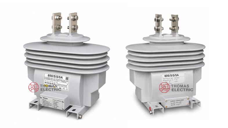
Product Display


Applications
- Outdoor 10 kV, 11 kV and 12 kV class distribution systems
- Outdoor substations, feeder bays and pole-mounted metering units
- Outdoor energy metering and current measurement circuits
- Relay protection circuits for overhead-line feeders and distribution transformers
- Medium-voltage outdoor switchgear, recloser panels and sectionalizing systems
- Projects requiring a weather-resistant CT with multi-secondary metering/protection outputs
Features
- Outdoor weather-resistant positioning: The product is designed for exposed outdoor operation, not only for indoor switchgear cabinet installation.
- Shed-type creepage structure: The external ribbed insulation body helps increase creepage distance and supports operation under rain, humidity and surface contamination.
- 4S multi-secondary configuration: Multiple secondary circuits allow separate functions such as metering, measurement, protection and backup protection.
- Wide current selection: The supplied data covers typical current ranges from 10 A to 2000 A for outdoor feeder and metering applications.
- Metering and protection accuracy: Typical combinations include 0.2S, 0.5, 5P10, 5P15, 5P20 and 5P30 according to circuit function.
- International voltage expression: Suitable for 10 kV, 11 kV and 12 kV class systems with 12/42/75 kV insulation coordination.
Principle
The LZZBJW-10/185/4S current transformer converts medium-voltage primary current into a standardized secondary current by electromagnetic induction. The primary current generates magnetic flux in the CT core, and the secondary windings provide proportional 5 A or 1 A signals to meters, relays and monitoring devices.
For outdoor applications, the selection logic is different from indoor CTs. In addition to ratio, burden and accuracy class, engineers should verify outdoor insulation level, creepage distance, weather exposure, surface pollution, top-terminal mechanical connection, short-time thermal current and rated dynamic current. For the 4S configuration, each secondary circuit should be assigned and checked independently.
Model Designation

| Code | Meaning |
|---|---|
| L | Current transformer |
| Z | Indoor/outdoor support-type current transformer structure family |
| Z | Epoxy resin casting insulation |
| B | Protection level available |
| J | Strengthened design series |
| W | Outdoor type / weather-resistant structure |
| 10 | 10 kV catalogue voltage class; used with 12 kV highest equipment voltage insulation coordination |
| 185 | 185 structure / body dimension code |
| 4S | Four-secondary schematic configuration |
Technical Data
| Item | Specification |
|---|---|
| Model | LZZBJW-10/185/4S |
| Installation condition | Outdoor |
| System voltage application | 10 kV, 11 kV and 12 kV class systems |
| Rated insulation level | 12/42/75 kV |
| Rated frequency | 50 Hz / 60 Hz |
| Rated secondary current | 5 A or 1 A |
| Rated primary current range | 10 A to 2000 A reference range according to supplied data |
| Accuracy class combinations | 0.2S/0.5/5P10, 0.2S/0.5/5P15, 0.2S/0.5/5P20, 0.2S/0.5/5P30 and project-specific combinations |
| Rated output | 20/20/100, 20/20/60, 20/20/40, 20/20/25, 30/30/120, 30/30/80, 30/30/50, 30/30/30 and project-specific VA configurations |
| Rated short-time thermal current | 150 × I1n, 200 × I1n, 32 kA, 50 kA, 63 kA, 80 kA or 100 kA reference according to current range |
| Rated dynamic current | 375 × I1n, 500 × I1n, 80 kA, 125 kA, 160 kA, 200 kA or 250 kA reference according to current range |
| Approximate weight | 33.5 kg reference according to supplied drawing |
| Applicable standards | GB 20840.1-2010, GB 20840.2-2014 and customer-specific requirements |
Selection Table
The following table summarizes the supplied selection data for website reference. Long accuracy and output values are arranged into multiple lines to improve readability on technical product pages.
| Rated
Primary Current (A) |
Accuracy
Class Combination |
Rated
Output(VA) |
Short-Time
Thermal Current |
Rated
Dynamic Current |
|---|---|---|---|---|
| 10–40 | 0.2S / 0.5 / 5P10 0.2S / 0.5 / 5P15 0.2S / 0.5 / 5P20 0.2S / 0.5 / 5P30 |
20 / 20 / 100 | 150 × I1n | 375 × I1n |
| 50–100 | 20 / 20 / 60 | 200 × I1n | 500 × I1n | |
| 150–250 | 20 / 20 / 25 | 32 kA | 80 kA | |
| 300–400 | 20 / 20 / 30 | 50 kA | 125 kA | |
| 500–600 | 20 / 20 / 20 | 63 kA | 160 kA | |
| 750–800 | 30 / 30 / 120 30 / 30 / 80 30 / 30 / 50 30 / 30 / 30 |
80 kA | 200 kA | |
| 1000–2000 | 30 / 30 / 50 / 50 30 / 30 / 30 / 30 30 / 30 / 25 / 25 30 / 30 / 15 / 15 |
100 kA | 250 kA | |
| Project-specific ratios | By technical agreement | By technical agreement | By technical agreement |
Note: If the required parameters exceed the above table range, final values shall be confirmed by agreement between manufacturer and purchaser. Nameplate data, approved drawings and factory test reports shall prevail.
4S Secondary Design
The 4S configuration is suitable for outdoor projects that require several independent secondary functions. Typical applications include energy metering, operating measurement, relay protection and backup protection. Each secondary core should be selected by its own accuracy class, rated output and connected burden.
| Secondary Circuit | Typical Function | Selection Focus |
|---|---|---|
| 1S1 / 1S2 | Metering or precision measurement | Accuracy class, burden and phase displacement |
| 2S1 / 2S2 | Panel measurement or monitoring | Rated output and instrument burden |
| 3S1 / 3S2 | Relay protection | Protection class, ALF and relay burden |
| 4S1 / 4S2 | Backup protection or auxiliary monitoring | Project-specific protection or monitoring requirement |
Outdoor Insulation
| Outdoor Factor | Engineering Focus | Selection Note |
|---|---|---|
| Shed-type insulation | Rain performance and surface creepage path | Check creepage distance and pollution level against the project environment. |
| Top primary terminals | Outdoor conductor connection and mechanical strength | Confirm terminal direction, bolt size and conductor stress before installation. |
| Secondary terminal box | Moisture protection and wiring reliability | Ensure sealing, cable outlet direction and grounding meet outdoor requirements. |
| Environmental exposure | Rain, humidity, dust, UV and temperature variation | Confirm outdoor service conditions before ordering. |
Service Conditions
- Installation location: outdoor medium-voltage power system
- System voltage: 10 kV, 11 kV and 12 kV class networks
- Rated frequency: 50 Hz / 60 Hz
- Rated secondary current: 5 A or 1 A
- Ambient temperature: -25°C to +40°C
- The installation environment shall be reviewed for pollution level, rain exposure, humidity, altitude, wind load and mechanical terminal stress.
- For coastal, high-humidity, heavy-pollution or high-altitude applications, creepage distance and insulation coordination must be confirmed by technical agreement.
Standards and Compliance
The LZZBJW-10/185/4S outdoor current transformer can be supplied according to GB 20840.1-2010, GB 20840.2-2014 and customer-specific requirements. For international projects, the product can be technically reviewed with reference to the IEC 61869 current transformer standard framework. Routine tests typically include ratio test, polarity verification, accuracy test, dielectric withstand test, insulation inspection and appearance inspection.
Installation and Dimensions

The product uses an outdoor ribbed insulation body with top primary terminals, base mounting points and a secondary terminal box. The supplied drawing shows different terminal plate layouts for current ranges such as 5 A < I1n < 800 A, 1000 A < I1n < 1600 A and 1600 A < I1n < 2000 A. The final outline drawing must be confirmed before conductor fabrication or outdoor installation.
Dimensions
| Item | Dimension / Note |
|---|---|
| Structure type | Outdoor epoxy cast-resin CT with shed-type creepage ribs |
| Primary terminal layout | Top terminal arrangement according to current range |
| Secondary terminal area | Outdoor secondary terminal box |
| Approximate weight | 33.5 kg reference |
| Mounting base | Base mounting holes according to approved drawing |
| Drawing confirmation | Required before conductor processing, installation or replacement |
Safety Notes
- Confirm model, voltage class, insulation level, current ratio and 4S secondary configuration before ordering.
- Check outdoor mounting base, top terminal direction, conductor stress and phase clearance before installation.
- Confirm secondary terminal box sealing, cable outlet direction and grounding arrangement.
- Connect P1/P2 and secondary terminals according to polarity markings and the project wiring diagram.
- The secondary circuit of a current transformer must not be open-circuited when the primary circuit is energized.
- Before disconnecting meters or relays, short-circuit the corresponding secondary circuit through a proper shorting device.
- Installation and maintenance shall be performed by qualified medium-voltage electrical personnel.
Ordering Info
- Product model: LZZBJW-10/185/4S
- System voltage: 10 kV, 11 kV or 12 kV
- Rated primary current and rated secondary current
- Secondary circuit function assignment for 4S configuration
- Accuracy class combination and rated output for each secondary circuit
- Rated insulation level and applicable GB / IEC requirement
- Rated short-time thermal current and rated dynamic current
- Outdoor pollution level, creepage requirement and service environment
- Mounting drawing, top terminal layout, conductor connection and cable outlet direction
- Quantity, certificates, routine test reports, labeling and packaging requirements
Selection Guide
- Confirm outdoor duty: Select LZZBJW-10/185/4S when the CT must operate outdoors under rain, humidity and pollution exposure.
- Confirm voltage class: Use it for 10 kV, 11 kV and 12 kV class systems with 12/42/75 kV insulation coordination.
- Assign 4S functions: Define each secondary circuit for metering, measurement, protection or backup protection.
- Select accuracy and output: Match 0.2S, 0.5 and 5P classes with the connected burden and relay requirement.
- Check outdoor insulation: Review creepage distance, shed structure, pollution level and environmental exposure.
- Verify withstand current: Confirm thermal and dynamic current values against the system short-circuit level.
- Approve final drawing: Confirm terminal layout, mounting base, secondary box direction and nameplate data before production.