Product Overview
The LZZW6-10 / LZZW-10/12 outdoor current transformer is a pillar-type, fully enclosed cast-insulation current transformer for outdoor medium-voltage distribution systems. It is used for current measurement, electric energy metering and relay protection in 10 kV, 11 kV and 12 kV class AC power systems with rated frequency of 50 Hz or 60 Hz.
This product should be positioned as an outdoor anti-pollution pillar-type CT, not as a normal indoor cast-resin switchgear CT. Its value is in outdoor insulation reliability: the resin-cast sealed body, pole-type support structure, anti-dirtiness design and partial-discharge control are intended for exposed service conditions such as humidity, dust, rain, surface contamination and outdoor distribution equipment installation.
Product Type
| Item | Specification |
|---|---|
| Product name | Pillar Type Fully Enclosed Outdoor Cast Insulation Current Transformer |
| Model series | LZZW6-10 / LZZW-10/12 |
| Installation condition | Outdoor |
| Structure | Pillar type, fully enclosed, solid cast-sealing insulation |
| System voltage application | 10 kV, 11 kV and 12 kV class medium-voltage systems |
| Rated insulation level | 12/42/75 kV |
| Rated frequency | 50 Hz / 60 Hz |
| Rated secondary current | 5 A / 1 A; 2 A can be supplied according to project requirement |
| Burden power factor | cosφ = 0.8 lagging |
| Anti-pollution class | Class II reference |
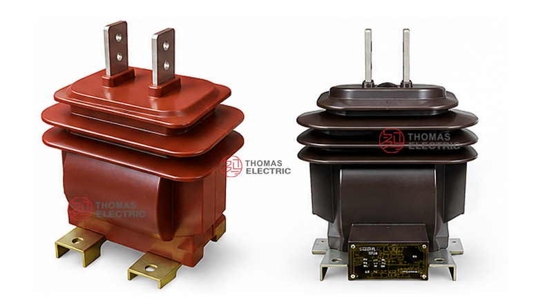
Product Display


Applications
- Outdoor 10 kV, 11 kV and 12 kV class distribution feeders
- Outdoor substations, pole-mounted equipment and open-air metering points
- Current measurement and electric energy metering circuits
- Relay protection circuits for outdoor switchgear and distribution lines
- Outdoor metering units and high-voltage metering boxes
- Projects requiring anti-pollution, moisture-resistant and fully enclosed outdoor CT construction
Features
- Outdoor anti-pollution positioning: The LZZW series is designed for exposed outdoor service where dust, humidity, rain and surface contamination must be considered.
- Pillar-type support structure: The pole-type body provides insulation support and mechanical stability for outdoor medium-voltage installation.
- Fully enclosed cast insulation: The primary conductor, secondary winding and magnetic core are sealed in resin to improve moisture resistance and dielectric stability.
- Measurement and protection selection: Typical combinations include 0.2S/0.2/10P, 0.2/10P, 0.5/10P and 0.5S/0.5/10P.
- 12/42/75 kV insulation coordination: Suitable for common 10 kV, 11 kV and 12 kV class systems.
- Variable-ratio capability: Multi-ratio structures can be manufactured according to project requirements and nameplate specification.
Principle
The LZZW6-10 / LZZW-10/12 current transformer converts medium-voltage primary current into a standardized secondary current through electromagnetic induction. Primary current generates magnetic flux in the core, and the secondary winding outputs a proportional 5 A or 1 A signal for meters, relays or monitoring devices.
For outdoor CT selection, the key engineering focus is not only current ratio and accuracy class. The outdoor insulation level, pollution class, creepage requirement, partial-discharge condition, short-time thermal current, dynamic current, mounting arrangement and secondary terminal protection must be reviewed together.
Model Designation

| Code | Meaning |
|---|---|
| L | Current transformer |
| Z | Pole type / pillar type support structure |
| Z | Solid cast-sealing insulation |
| W | Anti-dirtiness / outdoor anti-pollution design |
| 6 / 10 | Rated voltage class code |
| 10/12 | 10 kV catalogue class with 12 kV insulation coordination for 10 kV, 11 kV and 12 kV systems |
Technical Data
| Item | Specification |
|---|---|
| Model | LZZW6-10 / LZZW-10/12 |
| Installation condition | Outdoor |
| Rated voltage class | 10 kV, 11 kV and 12 kV class systems |
| Rated insulation level | 12/42/75 kV |
| Rated frequency | 50 Hz / 60 Hz |
| Rated secondary current | 5 A, 2 A or 1 A according to project requirement |
| Burden power factor | cosφ = 0.8 lagging |
| Accuracy class combinations | 0.2S/0.2/10P, 0.2/10P, 0.5/10P, 0.5S/0.5/10P and project-specific combinations |
| Rated output | 0.2: 10 VA; 0.2S: 10 VA; 0.5S: 10 VA; 0.5: 15 VA; 10P: 15 VA reference |
| Anti-pollution class | Class II reference |
| Partial discharge condition | In line with GB1208-2006 current transformer requirements |
| Applicable standards | IEC 60044-1, GB1208-2006 and customer-specific requirements |
Selection Table
The following table is arranged from the supplied technical data for preliminary website selection. Long accuracy and output values are separated into multiple lines to keep the table readable in responsive layouts.
| Rated Primary Current (A) |
Accuracy Class Combination |
Rated Output (VA) |
Rated Short-Time Thermal Current |
Rated Dynamic Current |
|---|---|---|---|---|
| 20–40 / 40 | 0.2S / 0.2 / 10P 0.2 / 10P or 0.5 / 10P 0.5S / 0.5 / 10P |
0.2: 10 0.2S: 10 0.5S: 10 0.5: 15 10P: 15 |
6.3 kA | 15 kA |
| 30–60 / 60 | 9 kA | 22.5 kA | ||
| 40–75 / 75 | 15 kA | 37.5 kA | ||
| 50–100 / 100 | 18 kA | 45 kA | ||
| 75–150 / 150 | 25 kA | 55 kA | ||
| 100–200 / 200 | 50 kA | 110 kA | ||
| 150–300 / 300 | 60 kA | 130 kA | ||
| 200–400 / 400 | ||||
| 300–600 / 600 | ||||
| 400–800 / 800 | ||||
| 500–1000 / 1000 | ||||
| 1200–1500 | 80 kA | 100 kA | ||
| 2000–3000 | 80 kA | 100 kA |
Note: If the required parameters exceed the listed table range, final values shall be confirmed by technical agreement between manufacturer and purchaser. Nameplate data and factory test reports shall prevail.
Outdoor Insulation
The main difference between LZZW outdoor CTs and indoor cast-resin CTs is the outdoor insulation requirement. The CT body must consider pollution exposure, surface wetting, rain, dust and long-term ultraviolet influence. For outdoor projects, confirm creepage distance, anti-pollution class and installation altitude before final selection.
| Outdoor Factor | Engineering Focus | Selection Note |
|---|---|---|
| Pollution exposure | Dust, salt mist, industrial pollution and surface contamination | Confirm anti-pollution class and creepage distance. |
| Moisture and rain | Outdoor humidity, wet surface and condensation | Use fully enclosed cast insulation and proper installation direction. |
| Insulation coordination | Power-frequency withstand and lightning impulse withstand | Confirm 12/42/75 kV or project-specific insulation level. |
| Partial discharge | Insulation quality under operating voltage | Confirm GB1208-2006 partial discharge requirements. |
Terminals
Primary terminals are arranged on the outdoor pillar-type CT body according to the approved outline drawing. Secondary terminals should be protected against moisture and connected according to the wiring diagram. Correct polarity marking is essential for metering, measurement and relay protection performance.
| Terminal Area | Function | Engineering Note |
|---|---|---|
| P1 / P2 | Primary current terminals | Connect according to the outdoor installation drawing and system current direction. |
| S1 / S2 | Secondary current output | Connect to meters, relays or monitoring devices according to polarity. |
| Grounding point | Safety grounding | Grounding shall comply with substation and outdoor equipment requirements. |
| Secondary shorting device | Maintenance safety | Short-circuit the secondary circuit before disconnecting instruments or relays. |
Service Conditions
- Installation location: outdoor medium-voltage distribution system
- System voltage: 10 kV, 11 kV and 12 kV class networks
- Rated frequency: 50 Hz / 60 Hz
- Rated secondary current: 5 A / 1 A, with 2 A available according to project requirement
- Outdoor anti-pollution requirement: class II reference
- The installation environment shall be checked for pollution severity, altitude, humidity, temperature, wind load and mounting stability.
- For coastal, high-humidity, heavy-pollution or high-altitude applications, creepage distance and insulation coordination must be technically confirmed.
Standards and Compliance
The LZZW6-10 / LZZW-10/12 outdoor current transformer can be manufactured according to IEC 60044-1, GB1208-2006 and special project requirements. The partial discharge test conditions follow GB1208-2006 current transformer requirements. For modern IEC projects, parameters may also be checked against the applicable IEC 61869 current transformer framework during technical agreement.
Installation and Dimensions

The product adopts an outdoor pillar-type structure. During installation, confirm the mounting base, primary terminal direction, phase clearance, secondary terminal protection, grounding point and creepage distance. Outdoor installation should avoid mechanical stress on the terminals and should keep secondary wiring protected against water ingress.
Dimensions
| Item | Dimension / Note |
|---|---|
| Structure type | Outdoor pillar-type fully enclosed cast insulation CT |
| Primary terminal layout | According to approved outline drawing |
| Secondary terminal box | Protected secondary wiring area according to project design |
| Mounting base | Outdoor mounting base or support bracket according to drawing |
| Creepage distance | Confirmed according to pollution level and project requirement |
| Drawing confirmation | Required before outdoor installation or replacement |
Safety Notes
- Confirm the complete model, voltage class, insulation level and outdoor anti-pollution requirement before ordering.
- Check the mounting base, phase clearance and primary terminal direction before installation.
- Confirm the secondary terminal sealing and cable outlet protection for outdoor service.
- Connect P1/P2 and S1/S2 according to polarity markings and the project wiring diagram.
- The secondary circuit of a current transformer must not be open-circuited when the primary circuit is energized.
- Before disconnecting meters or relays, short-circuit the corresponding secondary circuit through a proper shorting device.
- Installation and maintenance shall be performed by qualified medium-voltage electrical personnel.
Ordering Info
- Product model: LZZW6-10 or LZZW-10/12
- System voltage: 10 kV, 11 kV or 12 kV
- Rated primary current and rated secondary current
- Accuracy class combination and rated output
- Rated insulation level and outdoor pollution class requirement
- Rated short-time thermal current and rated dynamic current
- Partial discharge, creepage distance and standard requirement
- Outdoor installation drawing, terminal direction and mounting base details
- Quantity, certificates, routine test reports, labeling and packaging requirements
Selection Guide
- Confirm outdoor installation: Select this model when the CT will operate outdoors under humidity, pollution and weather exposure.
- Confirm voltage class: Use it for 10 kV, 11 kV and 12 kV class systems with 12/42/75 kV insulation coordination.
- Select current ratio: Choose the rated primary current according to feeder load, metering range and relay protection setting.
- Define accuracy combination: Select 0.2S, 0.2, 0.5, 0.5S or 10P combinations according to metering and protection requirements.
- Check outdoor insulation: Confirm anti-pollution class, creepage distance, partial discharge requirement and service environment.
- Verify withstand current: Match rated thermal and dynamic current with the system short-circuit level.
- Approve final drawing: Confirm terminal layout, mounting base, grounding point and secondary terminal protection before production.