Product Overview
The JSZW-10 voltage transformer is an indoor three-phase epoxy cast-resin voltage transformer for medium-voltage power systems. It is designed for voltage measurement, electric energy metering, voltage monitoring and relay protection in AC systems with rated frequency of 50Hz or 60Hz. For international product pages, this model should be presented as a 10kV, 11kV and 12kV class indoor cast-resin voltage transformer, rather than only a 10kV domestic model.
This product is different from the JSZW3-G mining combined-switch type and also different from the compact JSZW3 semi-enclosed version. The JSZW-10 series is better positioned as a general indoor three-phase cast-resin voltage transformer for neutral non-effectively grounded systems. It is mainly used in medium-voltage switchgear, metering panels, distribution rooms and industrial power systems where a stable three-phase voltage signal is required for meters, protection relays and monitoring devices.
The transformer adopts a three-phase integrated cast-resin insulated structure. The primary side is connected to the medium-voltage system through high-voltage bushings, while the secondary side provides standard voltage output for measurement, protection and residual-voltage functions. The product is suitable for indoor environments where compact installation, stable insulation performance and simplified three-phase wiring are required.
Product Type
| Item | Specification |
|---|---|
| Product name | Indoor Three-Phase Epoxy Cast-Resin Voltage Transformer |
| Model series | JSZW-10 / JSZW-11 / JSZW-12 |
| Structure | Indoor three-phase cast-resin insulated voltage transformer |
| Voltage class | 10kV, 11kV and 12kV class medium-voltage systems |
| Rated frequency | 50Hz / 60Hz |
| System grounding | Neutral non-effectively grounded power system |
| Typical secondary output | 100V / √3, 100V / 3, 110V / √3 or 110V / 3 by project requirement |
| Accuracy class | 0.2, 0.5, 1 for metering; 3P or 6P for protection / residual voltage circuit |
| Typical application | Voltage measurement, energy metering, voltage monitoring and relay protection |
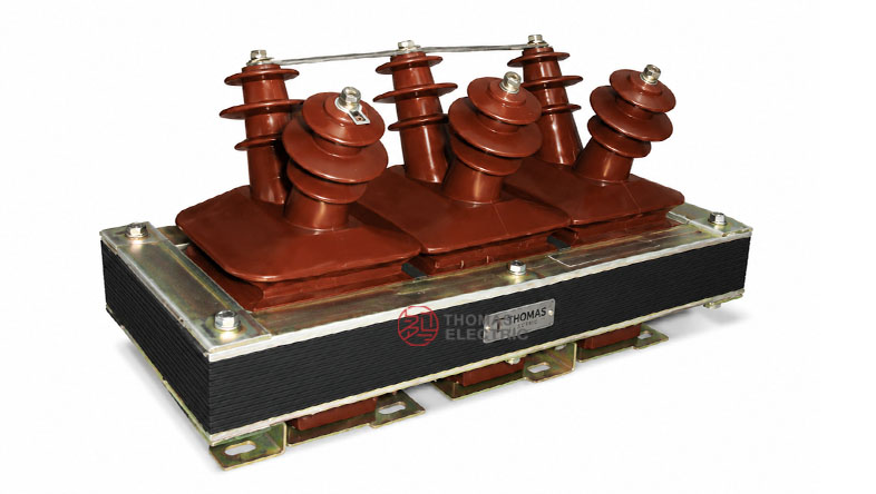
Product Display

Applications
- 10kV, 11kV and 12kV class indoor medium-voltage switchgear
- Voltage measurement and electric energy metering circuits
- Relay protection and voltage supervision circuits
- Residual-voltage monitoring and earth-fault detection circuits
- Industrial distribution rooms, utility metering panels and feeder cabinets
- Neutral non-effectively grounded or isolated-neutral power systems
- IEC-oriented export projects requiring 11kV / 12kV class voltage transformer documentation
Features
- General indoor VT positioning: The JSZW-10 series is suitable for standard indoor switchgear applications, not limited to mining combined switch equipment.
- Three-phase integrated design: One transformer body provides three-phase voltage transformation, reducing cabinet wiring and installation space.
- Epoxy cast-resin insulation: The cast-resin structure supports insulation strength, mechanical stability and indoor environmental resistance.
- Neutral non-effectively grounded systems: The product is suitable for voltage measurement and protection in systems where the neutral point is not effectively grounded.
- Metering and protection functions: Accuracy classes can be configured for voltage metering, measurement and protection circuits.
- International voltage expression: The page can include 10kV, 11kV and 12kV class wording for Southeast Asia, Middle East, Africa and IEC export projects.
Working Principle
The JSZW-10 voltage transformer operates according to electromagnetic induction. The primary winding is connected to the medium-voltage system, and the secondary winding outputs a reduced standard voltage signal for meters, relays, monitoring instruments and control devices. The secondary circuit is electrically isolated from the primary high-voltage circuit, improving measurement safety and allowing standardized low-voltage signal acquisition.
For metering applications, the transformer must maintain voltage ratio and phase accuracy within the rated burden. For protection or residual-voltage applications, the protection-class winding must provide a dependable voltage signal under abnormal system conditions. Correct selection of voltage ratio, secondary voltage, accuracy class, rated output and wiring method is essential for stable operation.
Model Designation

| Code | Meaning |
|---|---|
| J | Voltage transformer / potential transformer |
| S | Three-phase configuration |
| Z | Cast-resin insulated structure |
| W | Five props / five-post structure reference |
| 10 | 10kV class model reference; can be documented for 11kV / 12kV class projects by confirmation |
Technical Data
| Item | Specification |
|---|---|
| Model series | JSZW-10 / JSZW-11 / JSZW-12 |
| Rated voltage class | 10kV, 11kV and 12kV class indoor systems |
| Rated insulation level | 12/42/75kV by project confirmation for 10kV, 11kV and 12kV class equipment |
| Rated frequency | 50Hz / 60Hz |
| Ambient temperature | -5°C to +40°C |
| Altitude | Up to 1000m above sea level unless otherwise specified |
| Relative humidity | ≤85% at 20°C reference |
| Load power factor | cosφ = 0.8 lagging |
| Surface creepage distance | Designed to meet the required pollution class by project specification |
| Accuracy class | 0.2, 0.5, 1 for metering; 3P or 6P for protection / residual voltage circuit |
| Applicable standards | IEC 61869-3, IEC 61869-1, GB/T 20840.3 and project-specific requirements |
Selection Table
The following selection table uses international voltage-class wording. Long cells are split into multiple lines for responsive website display.
| Model | Rated Voltage Ratio |
Accuracy Class Combination |
Rated Output Reference |
Application Note |
|---|---|---|---|---|
| JSZW-10 | 10000 / √3 : 100 / √3 : 100 / 3 or project-specified ratio |
0.2 / 3P or 0.2 / 6P | By technical agreement | 10kV class indoor switchgear |
| 0.5 / 3P or 0.5 / 6P | By technical agreement | |||
| 1 / 3P or 1 / 6P | By technical agreement | |||
| JSZW-11 | 11000 / √3 : 110 / √3 : 110 / 3 or project-specified ratio |
0.2 / 3P or 0.2 / 6P | By technical agreement | 11kV IEC-oriented switchgear |
| 0.5 / 3P or 0.5 / 6P | By technical agreement | |||
| 1 / 3P or 1 / 6P | By technical agreement | |||
| JSZW-12 | 12000 / √3 : 110 / √3 : 110 / 3 or project-specified ratio |
0.2 / 3P or 0.2 / 6P | By technical agreement | 12kV equipment class projects |
| 0.5 / 3P or 0.5 / 6P | By technical agreement | |||
| 1 / 3P or 1 / 6P | By technical agreement |
Note: Rated output and accuracy class should be selected as matched combinations. Parameters beyond catalogue data shall be confirmed by technical agreement between manufacturer and purchaser.
Construction
- Indoor three-phase cast-resin insulated structure
- Three high-voltage bushings arranged on the upper side
- Secondary terminal panel arranged on the lower side for convenient wiring
- Suitable for neutral non-effectively grounded power systems
- Designed for voltage measurement, metering and relay protection applications
Windings
The JSZW-10 series normally includes primary windings, measuring secondary windings and residual-voltage or protection windings. Typical primary terminals are marked A, B, C and N. Secondary terminals may be marked a, b, c, n, while residual-voltage terminals may be marked da / dn or according to the approved wiring diagram.
| Winding / Terminal | Function | Engineering Note |
|---|---|---|
| A, B, C | Primary phase terminals | Connected to the medium-voltage three-phase system. |
| N | Primary neutral terminal | Connection depends on system grounding and approved wiring diagram. |
| a, b, c, n | Secondary voltage terminals | Used for meters, instruments and monitoring devices. |
| da / dn | Residual-voltage output | Used for open-delta residual-voltage detection and protection functions. |
Wiring Diagram

The JSZW-10 series can be wired in three-phase voltage transformer circuits according to the system grounding mode and protection scheme. The routine wiring diagram shown in the sample includes primary phase terminals and secondary voltage / residual-voltage outputs. The final connection must follow the approved terminal drawing and project schematic.
Service Conditions
- Installation altitude: up to 1000m above sea level unless otherwise specified
- Ambient temperature: -5°C to +40°C
- Relative humidity: not more than 85% at 20°C reference
- Installation environment should be free from gas, steam, chemical deposition, pollution, explosive gas or corrosive gas that may seriously affect insulation.
- The installation location should be free from severe vibration, chatter or impact.
- For tropical, coastal, high-altitude or high-pollution projects, creepage distance and insulation requirements should be confirmed before ordering.
Standards and Compliance
The JSZW-10 series can be specified according to IEC 61869-3 for inductive voltage transformers and IEC 61869-1 for general instrument transformer requirements. Older catalogue information may refer to earlier domestic voltage transformer standards, but international product pages should use IEC 61869-based wording for export projects. Routine tests may include ratio test, polarity test, accuracy verification, insulation test and power-frequency withstand test according to the agreed standard.
Installation and Dimensions

Dimensions
Final dimensions should be confirmed by the approved outline drawing. For website description, the JSZW-10 series can be described as a compact three-phase integrated cast-resin VT with top bushings, bottom secondary terminals and a base frame for indoor switchgear installation.
| Dimension Item | Engineering Requirement |
|---|---|
| Phase spacing | Confirm according to selected voltage class and outline drawing. |
| Overall width | Confirm with switchgear layout and bushing clearance. |
| Overall height | Confirm cabinet top clearance and high-voltage bushing space. |
| Secondary terminal access | Reserve enough wiring and maintenance space in front of the terminal panel. |
| Mounting base | Mounting hole size and position must follow the approved drawing. |
Before production or switchgear layout design, confirm the voltage ratio, secondary winding quantity, wiring diagram, terminal direction, bushing clearance, mounting hole distance and grounding arrangement. Because the JSZW-10 series is a three-phase integrated VT, sufficient space must be reserved for top high-voltage bushings and lower secondary terminal wiring.
Safety Notes
- Confirm voltage class, voltage ratio, insulation level, accuracy class and rated output before production.
- Check system grounding mode before selecting the wiring diagram.
- Secondary circuits of voltage transformers shall not be short-circuited during operation.
- Secondary circuits should be protected by suitable fuses or miniature circuit breakers.
- Before maintenance, de-energize the primary circuit and follow lockout/tagout safety procedures.
- One point of the secondary circuit should be grounded according to project electrical safety practice.
- Installation and commissioning shall be performed by qualified medium-voltage electrical personnel.
Ordering Info
- Product model: JSZW-10, JSZW-11 or JSZW-12
- Voltage class: 10kV, 11kV or 12kV class
- Rated voltage ratio, including primary voltage and secondary voltage
- Accuracy class and rated output for each secondary winding
- Residual-voltage winding requirement and open-delta output voltage
- Wiring diagram and terminal marking requirement
- Insulation level, creepage distance and pollution class requirement
- Installation drawing, mounting hole layout and switchgear structure
- Applicable IEC standard, routine test report and certificate requirements
- Quantity, label language, packaging and project documentation requirements
Selection Guide
- Confirm system voltage: Use 10kV, 11kV or 12kV class according to the project. For IEC export pages, include 11kV and 12kV class wording.
- Select voltage ratio: Choose 10000/√3, 11000/√3 or 12000/√3 primary ratio according to the system voltage and local secondary-voltage practice.
- Select secondary voltage: Common outputs include 100/√3, 100/3, 110/√3 and 110/3 according to meter and relay requirements.
- Define accuracy class: Use 0.2 or 0.5 for metering and 3P or 6P for protection / residual-voltage functions.
- Check burden: Confirm total burden of meters, relays and wiring does not exceed the selected rated output.
- Confirm wiring: Choose the wiring scheme according to the neutral grounding mode and residual-voltage protection requirement.
- Approve dimensions: Confirm bushing clearance, terminal access and mounting holes before switchgear production.