Product Overview
The LDC(D)-10 / LMC(D)-10 current transformer is an indoor wall-through type current transformer for medium-voltage AC power systems. It is used for current measurement, electric energy metering, signal sampling, relay protection, and microcomputer-based protection in 10kV, 11kV, and 12kV class power distribution equipment.
This product family includes wall-through and bus-type structures for switchgear and distribution equipment where the primary conductor passes through or connects through the transformer body. The LMC(D)-10 version is used for wall-through / bus-type installations, while the LDC(D)-10 series is used for indoor current measurement and protection applications in medium-voltage systems. The D version is used where differential protection or protection-oriented secondary configuration is required.
For international projects, the product can be specified with IEC-oriented 12kV-class insulation coordination. Typical insulation level is 12/42/75kV for 10kV, 11kV, and 12kV systems. The structure is compact, lightweight, and convenient for switchgear installation, while providing reliable secondary current output for metering and protection devices.
Product Type
| Item | Specification |
|---|---|
| Product name | Indoor Wall-Through Type Current Transformer |
| Model series | LDC-10 / LDCD-10 / LDCQ-10 / LDCQD-10 / LMC-10 / LMCD-10 |
| Product structure | Indoor wall-through type / bus-type current transformer for MV switchgear |
| Voltage class | 10kV, 11kV, and 12kV medium-voltage systems |
| Highest voltage for equipment | 12kV class |
| Rated insulation level | 12/42/75kV reference for IEC 12kV-class insulation coordination |
| Rated frequency | 50Hz / 60Hz |
| Rated secondary current | 5A standard; 1A available according to project requirement |
| Application type | Current measurement, energy metering, signal sampling, relay protection, microcomputer protection |
| Installation location | Indoor switchgear, distribution cabinet, wall-through panel, and MV power equipment |
| Applicable standard | IEC 61869-1 / IEC 61869-2; IEC 60044-1 can be referenced for legacy projects |
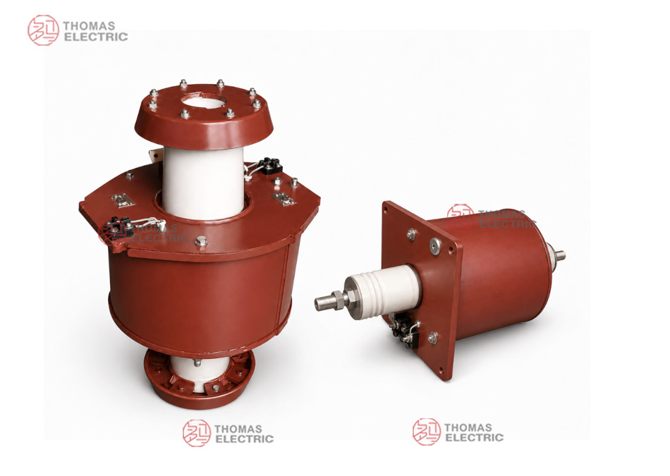
Product Display
-10, LMC(D)-10 Indoor Wall-Through Type Current Transformer Thomas Electric")
-10, LMC(D)-10 Indoor Wall-Through Type Current Transformer Thomas Electric")
Applications
- 10kV, 11kV, and 12kV indoor medium-voltage switchgear
- Power supply and distribution equipment for current measurement and energy metering
- Signal sampling circuits for intelligent monitoring devices
- Relay protection and microcomputer protection systems
- Wall-through installation where the CT also provides insulation separation between compartments
- High-current bus-type applications such as 2000A, 3000A, 4000A, and 5000A feeders
Features
- Wall-through structure: Suitable for medium-voltage cabinets where primary conductors pass through switchgear partitions or insulated barriers.
- Multiple model variants: LDC, LDCD, LDCQ, LDCQD, LMC, and LMCD variants support different measurement, protection, bus-type, and differential protection configurations.
- IEC voltage expression: Can be specified for 10kV, 11kV, and 12kV systems with 12/42/75kV insulation coordination.
- Measurement and protection outputs: Supports metering classes such as 0.5, 1, and 3, as well as 10P protection configurations.
- High-current capability: LMC / LMCD structures support high primary current ratios such as 2000/5, 3000/5, 4000/5, and 5000/5.
- Compact installation: Designed for switchgear integration with small volume, low weight, and convenient installation.
Working Principle
The LDC(D)-10 / LMC(D)-10 current transformer operates according to electromagnetic induction. The primary current in the conductor or busbar produces magnetic flux in the CT core, and the secondary winding outputs a proportional current signal to meters, protection relays, or monitoring devices. The insulation structure separates the medium-voltage primary circuit from the low-voltage secondary circuit and supports safe signal transmission under rated service conditions.
For metering circuits, the CT should maintain the specified ratio accuracy and phase displacement under the rated secondary burden. For protection and microcomputer protection circuits, the protection winding should supply a reliable fault-current signal and coordinate with relay setting, rated burden, accuracy limit factor, and short-circuit withstand level.
Model Designation
-10, LMC(D)-10 Indoor Wall-Through Type Current Transformer Thomas Electric")
The model designation identifies the current transformer type, wall-through or bus-type structure, differential protection option, and voltage class.
| Code | Meaning |
|---|---|
| L | Current transformer |
| D | Wall-through / special indoor switchgear structure |
| M | Bus type structure |
| C | Wall-through insulation structure according to model series |
| D in brackets | Differential protection version or protection-oriented configuration |
| Q | Enhanced or special structural version according to project configuration |
| 10 | Voltage class identification; used for 10kV systems and IEC 12kV-class insulation coordination for 10kV, 11kV, and 12kV projects |
Model coverage: This product page covers LDC-10, LDCD-10, LDCQ-10, LDCQD-10, LMC-10, and LMCD-10. Final model selection should be confirmed according to current ratio, switchgear installation type, insulation requirement, metering/protection configuration, and approved drawing.
Technical Data
| Item | Specification |
|---|---|
| Rated voltage class | 10kV / 11kV / 12kV medium-voltage systems |
| Highest voltage for equipment | 12kV class |
| Rated insulation level | 12/42/75kV reference |
| Rated frequency | 50Hz / 60Hz |
| Rated primary current | 400A to 5000A reference range depending on model; customized ratios available |
| Rated secondary current | 5A standard; 1A available according to project requirement |
| Accuracy class combination | 0.5 / 0.5, 1 / 1, 0.5 / 3, 10P / 0.5, 10P / 1, 10P / 3, 10P / 10P |
| Rated output | 20VA / 30VA / 50VA for metering classes; 15VA for protection class reference |
| Protection class | 10P15 or 10P20 according to model and protection requirement |
| Installation method | Indoor wall-through or bus-type installation according to switchgear layout |
| Applicable standard | IEC 61869-1 / IEC 61869-2; IEC 60044-1 can be referenced for legacy specification |
Terminal Marking
The LDC(D)-10 / LMC(D)-10 current transformer can be supplied with measuring, metering, protection, or differential protection secondary winding configurations. Terminal layout shall be confirmed according to the selected model and switchgear drawing.
| Terminal Marking | Function | Application Note |
|---|---|---|
| P1 / P2 | Primary terminals | The reference primary current direction is normally defined from P1 to P2. |
| 1S1 / 1S2 | First secondary winding | Usually used for metering, measurement, or signal sampling. |
| 2S1 / 2S2 | Second secondary winding | Usually used for relay protection, microcomputer protection, or differential protection. |
| Grounding terminal | Secondary grounding point | Grounding shall follow project wiring diagram and electrical safety requirements. |
Terminal markings follow standard CT polarity conventions. Correct terminal identification shall be observed to ensure metering accuracy, relay protection performance, and safe maintenance. The secondary circuit must not be open-circuited when the primary circuit is energized.
Selection Table
| Type | Rated
Current Ratio |
Accuracy
Class Combination |
Measuring
Output (VA) |
Protection
Output (VA) |
Protection
Class |
Short-Time
Thermal Current |
Rated
Dynamic Current |
|---|---|---|---|---|---|---|---|
| LDC-10 | 600/5 | 0.5 / 0.5 1 / 1 0.5 / 3 |
20 / 20 / 50 | — | — | 48kA | 78kA |
| 750/5 | 60kA | 90kA | |||||
| 1000/5 | 80kA | 90kA | |||||
| 1500/5 | 120kA | 99kA | |||||
| LDCD-10 | 600/5 | 10P / 0.5 10P / 1 10P / 10P |
20 / 20 | 15 | 10P20 | 48kA | 78kA |
| 750/5 | 60kA | 79kA | |||||
| 1000/5 | 80kA | 90kA | |||||
| 1500/5 | 120kA | 99kA | |||||
| LDCQ-10 | 400/5 | 1 / 1 1 / 3 |
20 / 50 | — | — | 48kA | 80kA |
| 600/5 | 72kA | 90kA | |||||
| 750/5 | 90kA | 90kA | |||||
| LDCQD-10 | 600/5 | 10P / 0.5 10P / 1 10P / 3 10P / 10P |
20 / 20 / 50 | 15 | 10P20 | 72kA | 78kA |
| 750/5 | 90kA | 79kA | |||||
| 1000/5 | 120kA | 90kA | |||||
| LMC-10 | 2000/5 | 0.5 / 0.5 0.5 / 3 |
30 / 50 | — | 10P15 reference for protection configuration | Project-specific | Project-specific |
| 3000/5 | |||||||
| 4000/5 | |||||||
| 5000/5 | |||||||
| LMCD-10 | 2000/5 | 10P / 0.5 10P / 3 10P / 10P |
30 / 50 | 15 | |||
| 3000/5 | |||||||
| 4000/5 | |||||||
| 5000/5 |
Note: The selection table is for preliminary engineering reference. Final current ratio, secondary current, accuracy class combination, rated output, protection class, short-time thermal current, dynamic current, insulation level, and terminal arrangement shall be confirmed according to approved drawing, nameplate, and factory test report.
LMC Data
| Item | LMC(D)-10 Reference Data |
|---|---|
| Rated primary current | 200A / 3000A / 4000A / 5000A reference options according to specification |
| Rated secondary current | 5A |
| Rated frequency | 50Hz |
| Rated output for class 0.5 | 10VA |
| Rated output for class B / protection reference | 15VA |
| Insulation level | 10/42/75kV reference in legacy data; IEC 12/42/75kV can be specified for 12kV-class projects |
| Short-time thermal current | 75 × I1n reference |
| Rated dynamic current | 2.5 × Ith reference |
| 10% multiple | 10 |
Service Conditions
- Installation location: indoor medium-voltage switchgear or wall-through panel
- System voltage: 10kV, 11kV, or 12kV class
- Rated frequency: 50Hz / 60Hz
- Rated insulation level: 12/42/75kV reference for IEC-style 12kV-class projects
- Ambient temperature: -5°C to +40°C reference range
- Suitable for indoor switchgear with controlled humidity, pollution, and condensation conditions
- The installation site should be free from severe vibration, corrosive gas, explosive medium, heavy conductive dust, and abnormal condensation.
- For high-current busbar applications, heat dissipation, clearance, and mechanical fixing must be confirmed with the switchgear design.
Standards and Compliance
The LDC(D)-10 / LMC(D)-10 current transformer can be supplied according to IEC 61869-1 and IEC 61869-2. IEC 60044-1 may be referenced for legacy project specifications. Routine tests, dielectric tests, polarity verification, ratio test, accuracy test, insulation resistance, and partial discharge requirements should be confirmed according to the final technical agreement.
Installation and Dimensions
-10, LMC(D)-10 Indoor Wall-Through Type Current Transformer Thomas Electric")
The LDC(D)-10 / LMC(D)-10 series is designed for indoor wall-through or bus-type switchgear installation. The primary conductor arrangement, insulation body, secondary terminal box, mounting holes, creepage distance, and cabinet interface shall be confirmed according to the approved outline drawing before switchgear design or batch production.
Outline Data
| Item | Selection Note |
|---|---|
| Mechanical structure | Indoor wall-through / bus-type current transformer |
| Primary connection | Wall-through conductor, busbar, or switchgear connection according to model |
| Secondary terminals | Terminal block arrangement according to selected winding configuration |
| Mounting method | Switchgear-mounted wall-through installation according to approved drawing |
| Drawing confirmation | Final outline, creepage distance, terminal direction, and mounting dimensions shall be confirmed before production |
Safety Notes
- Confirm the model, voltage class, current ratio, secondary current, accuracy class, rated output, insulation level, and wiring arrangement before installation.
- Check the primary conductor layout, wall-through opening, busbar clearance, phase-to-ground clearance, and switchgear layout against the approved drawing.
- Connect secondary terminals according to terminal markings and the project wiring diagram.
- The secondary circuit of a current transformer must not be left open when the primary circuit is energized.
- During meter or relay maintenance, short-circuit the CT secondary circuit before disconnecting any secondary wiring.
- Secondary grounding shall follow the project specification and local electrical safety requirements.
- Installation and maintenance shall be performed by qualified medium-voltage electrical personnel.
Ordering Info
Please provide the following information when ordering or requesting a quotation:
- Product model: LDC-10, LDCD-10, LDCQ-10, LDCQD-10, LMC-10, or LMCD-10
- System voltage: 10kV, 11kV, or 12kV
- Rated primary current / current transformation ratio
- Rated secondary current: 1A or 5A
- Accuracy class and rated output requirement for each secondary core
- Protection class requirement, if 10P output is needed
- Wall-through structure, busbar size, or switchgear interface requirement
- Insulation level and applicable IEC standard
- Switchgear type, installation layout, terminal direction, and required outline drawing
- Quantity, labeling, certificates, routine test reports, and packaging requirements
Selection Tips
- Confirm structure type: Select LDC / LDCD / LDCQ / LDCQD for wall-through measurement and protection applications, and LMC / LMCD for high-current bus-type applications.
- Confirm voltage class: Use IEC-style 12/42/75kV insulation coordination for 10kV, 11kV, and 12kV systems.
- Confirm primary current: Select the current ratio according to feeder load, busbar current, metering range, and protection setting range.
- Confirm secondary current: Select 5A or 1A according to meters, relays, cable length, and burden calculation.
- Define core function: Specify whether each secondary core is used for metering, signal sampling, relay protection, or differential protection.
- Check rated burden: The total burden of meters, relays, and secondary cables must not exceed the rated output of each secondary core.
- Confirm drawings: Check outline dimensions, wall-through interface, terminal direction, and switchgear clearance before production.